
Permeable gas assembly for gas delivery

a gas valve and permeable technology, applied in the direction of water supply installation, valve operating means/release devices, transportation and packaging, etc., can solve the problems of high concentration of arsine in the area, extremely toxic arsine gas, and wide range of hazardous situations in the arsine cylinder in production environments

Inactive Publication Date: 2005-08-30
ENTEGRIS INC
View PDF10 Cites 5 Cited by
  • Summary
  • Abstract
  • Description
  • Claims
  • Application Information

AI Technical Summary

Benefits of technology

"The present invention is about a gas delivery valve device that allows controlled communication between a fluid source and a processing tool. The valve device has a permeable valve seat member and a valve member that can move between a sealing position and an open position. The valve member has a first end and a second end, with the first end positioned in the inlet port and the second end positioned in the outlet port. The valve member has a permeable valve seat member with an abutting first end that can engage with the valve member to control its movement. The valve member has a first end extension with a reduced cross-sectional dimension to allow fluid to pass through it. The valve member can be made of a fluid permeable material to transfer fluid from the source to the processing tool. The invention also includes a method for discharging fluid from a container to a processing tool while reducing uncontrolled discharge of fluid from the container."

Problems solved by technology

Due to their extreme toxicity and high vapor pressure, their use, transportation and storage raise significant safety concerns for the semiconductor industry.
For example, arsine is an extremely toxic gas that is used by the semiconductor industry and typically stored in pressurized containers at about 250 psi.
The handling of arsine cylinders in production environments presents a wide variety of hazardous situations.
If the leak was large, the contamination could occur in a few minutes, which would mean that for many hours there would be extremely deadly concentrations in the area near the source of the spill.
However, these valves are subject to leakages of the highly pressurized gas along valve stems.
Unless some provision is made for preventing such leakage, the build-up of high pressure gas leakage in trapped volumes within the valve device can introduce an unintended bias into the regulator and produced distortion of the delivery control.
Clearly, in the case of inflammatory gas or explosive gases the possible accumulation of released gas in a confined area becomes a serious health and safety hazard, and an open port is not an option.
However, the purity of the gas is reduced due to residual absorbant material that may be entrained within the discharging gas.

Method used


Image

  • Permeable gas assembly for gas delivery
  • Permeable gas assembly for gas delivery
  • Permeable gas assembly for gas delivery

Examples


Embodiment Construction

[0058]In accordance with the present invention, controlled discharge of a pressurized fluid, such as a pressurized toxic gas from a fluid source is accomplished by diffusing the gas through a permeable section of a valve assembly device.

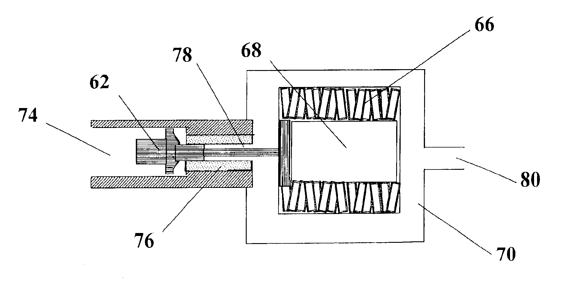
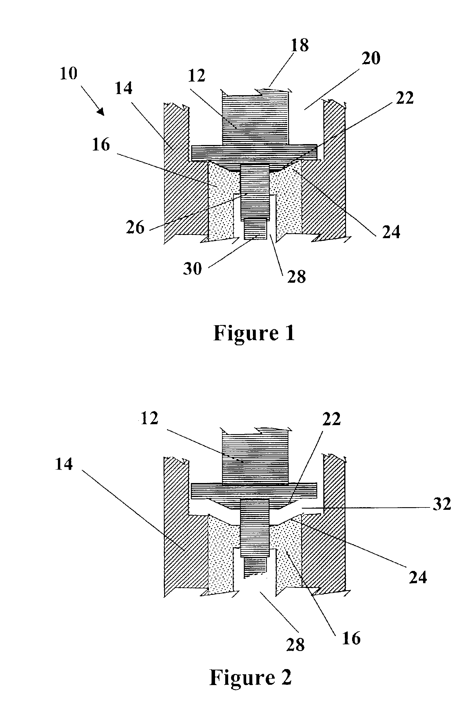
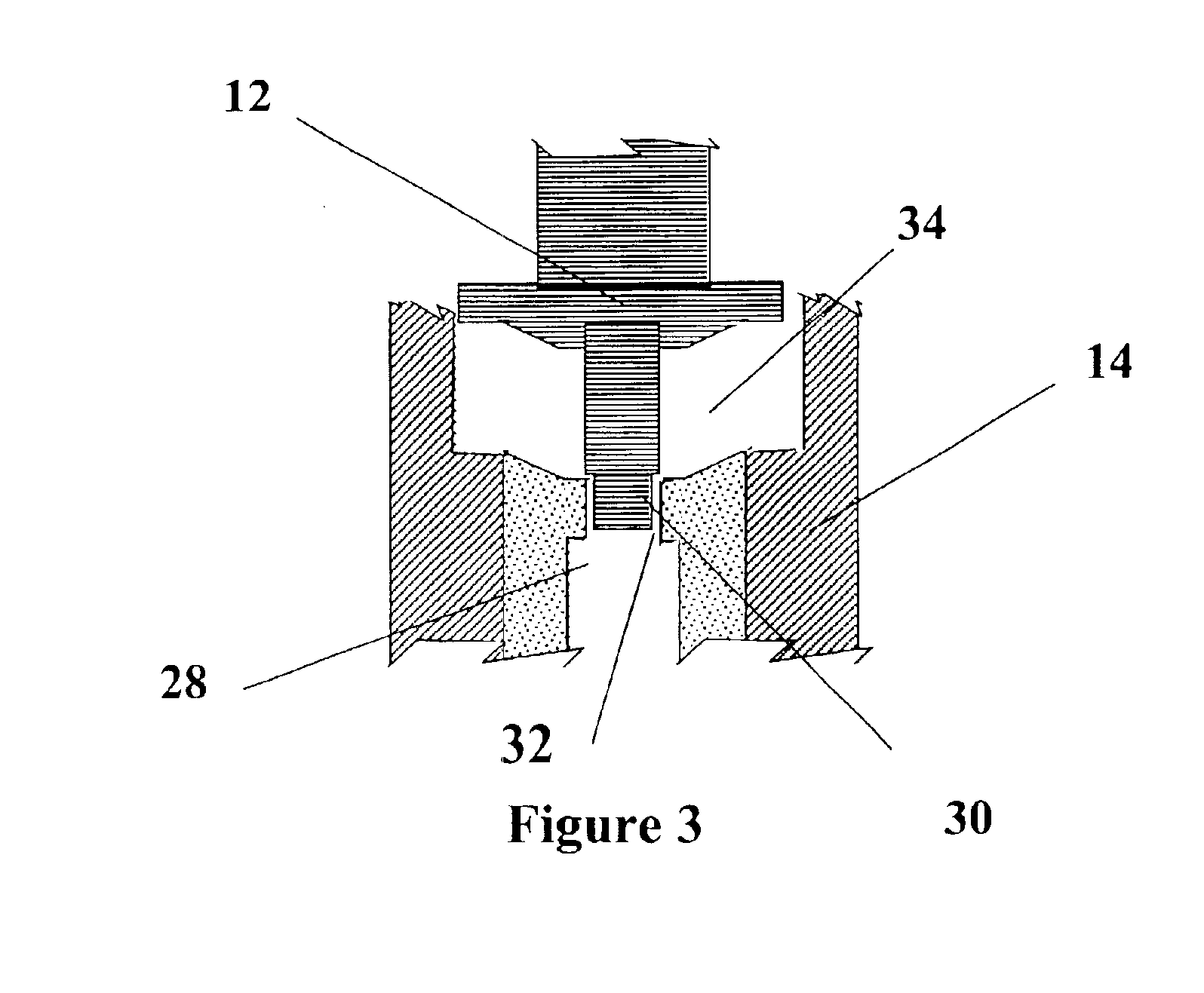
[0059]Referring to FIGS. 1-3, a valve assembly device in accordance with the present invention is generally depicted at 10 having a valve member 12 (poppet) and a valve seat member 14. Enclosed within the valve seat member is an insert 16 fabricated of a permeable material for diffusing gas therethrough. Although not shown, a source of fluid under pressure is preferably disposed immediately upstream from the valve assembly. Downstream of the valve assembly is a processing tool (not shown) that requires fluid at low pressure. The valve assembly device of the present invention controls passage of fluid from the source to the downstream tool.

[0060]Valve member 12 comprises a first end extension 18 which in FIGS. 1-3 extends axially outward and is of suf...


PUM


Abstract

A valve assembly for controlling gas delivery from a higher pressure fluid source to a lower pressure processing tool comprising a valve poppet movingly engageable with a valve seating member and a fluid permeable insert positioned between the valve poppet and the valve seating member that is unexposed to flowing fluid when the valve poppet is in a closed position thereby preventing fluid flow through the valve assembly and provides a diffusional path for transfer of all flowing fluid when the valve poppet is in an open position. The permeable insert can be inserted into the sealable and engageable surface of either the valve seat member or the valve poppet.

Description

BACKGROUND OF INVENTION[0001]1. Field of the Invention[0002]The present invention relates to a gas valve assembly, and more particularly, to a permeable gas valve assembly that controls fluid flow from a downstream fluid source to an upstream processing tool.[0003]2. Description of the Related Art[0004]Many industrial processing and manufacturing applications require the use of highly toxic fluids. The manufacture of semiconductor materials represents one such application wherein the safe storage and handling of highly toxic hydridic or halidic gases becomes necessary. Examples of such gases include silane, germane, ammonia, phosphine, arsine, stibine, hydrogen sulfide, hydrogen selenide, hydrogen telluride, and other halide compounds. As a result of toxicity and safety considerations, these gases must be carefully stored and handled in the industrial process facility. The semiconductor industry in particular relies on the gaseous hydrides of arsine (AsH3) and phosphine (PH3) as sou...

Claims


Application Information

Patent Timeline
Patent Type & Authority Patents(United States)
IPC IPC(8): F16K25/00F16K1/00F16K1/30
CPCF16K1/303F16K25/00F17C2205/0338F17C2205/0391Y10T137/0318Y10T137/7793Y10T137/7823Y10T137/86759Y10T137/86887H01L21/02
Inventor TOM, GLENN
Owner ENTEGRIS INC
Learn More