Hybrid analog/digital phase-lock loop for low-jitter synchronization

a phase-lock loop and analog/digital technology, applied in the field of synchronizing loops for providing low-jitter synchronized clock signals, can solve the problems of limited effective information update rate in the phase comparator of the apll, limitations on the jitter-reduction performance obtainable for a given application, and place a limit on the performance of the synchronizing circui

Active Publication Date: 2010-03-16
CIRRUS LOGIC INC
View PDF14 Cites 29 Cited by
  • Summary
  • Abstract
  • Description
  • Claims
  • Application Information

AI Technical Summary

Problems solved by technology

However, the intermediate clock signal frequency places a limit on the performance of the synchronizing circuit, since the intermediate clock signal frequency typically cannot exceed the divided output clock used for phase comparison in the APLL.
Furthermore, the effective information update rate in the phase comparator of the APLL is limited to a single bit of information at the intermediate clock signal frequency.
The constraints on the above-described synchronization circuit reduce applicability of the circuit and place limitations on the jitter-reduction performance obtainable for a given application.

Method used


Image

  • Hybrid analog/digital phase-lock loop for low-jitter synchronization
  • Hybrid analog/digital phase-lock loop for low-jitter synchronization
  • Hybrid analog/digital phase-lock loop for low-jitter synchronization

Examples


Embodiment Construction

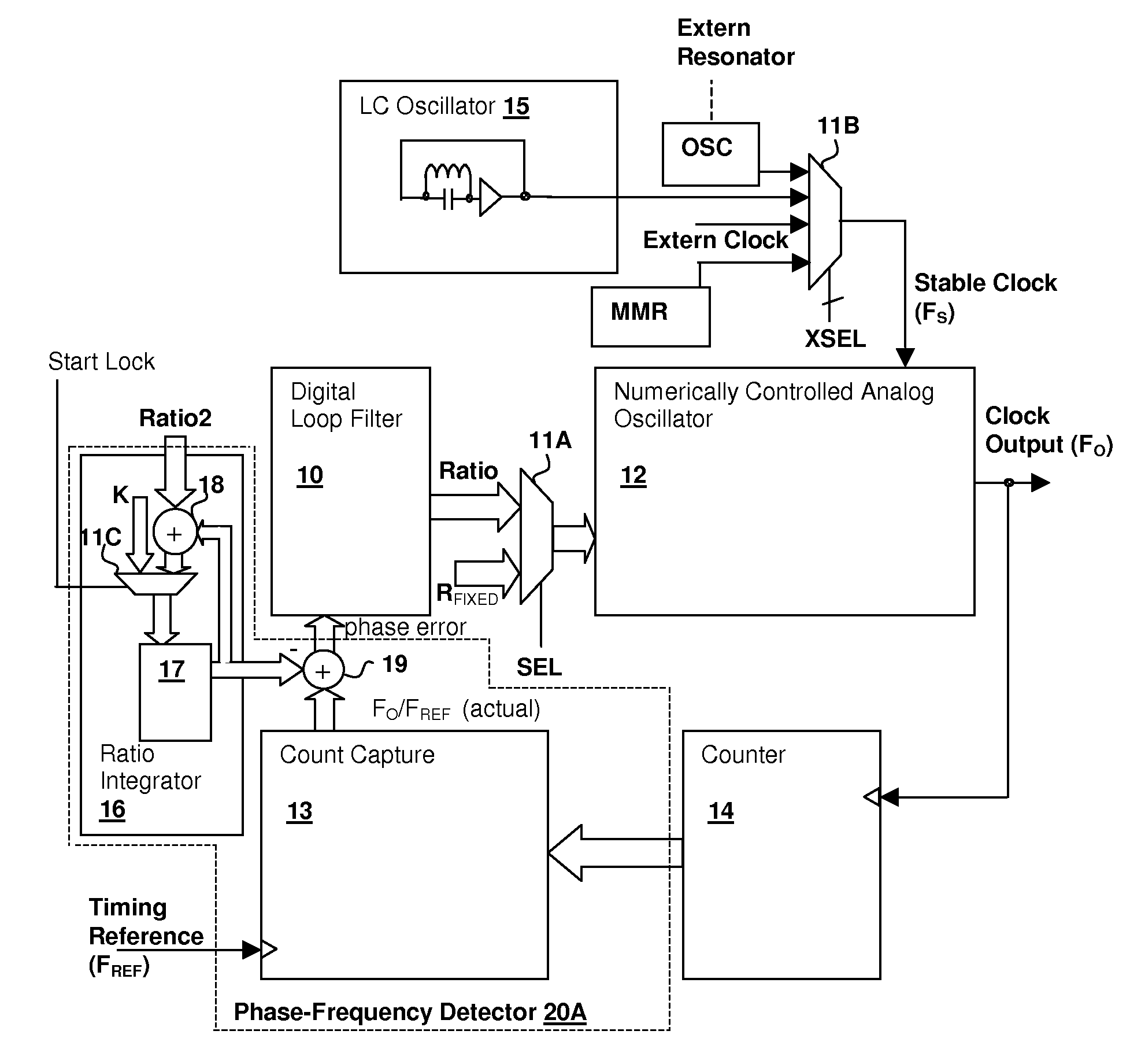
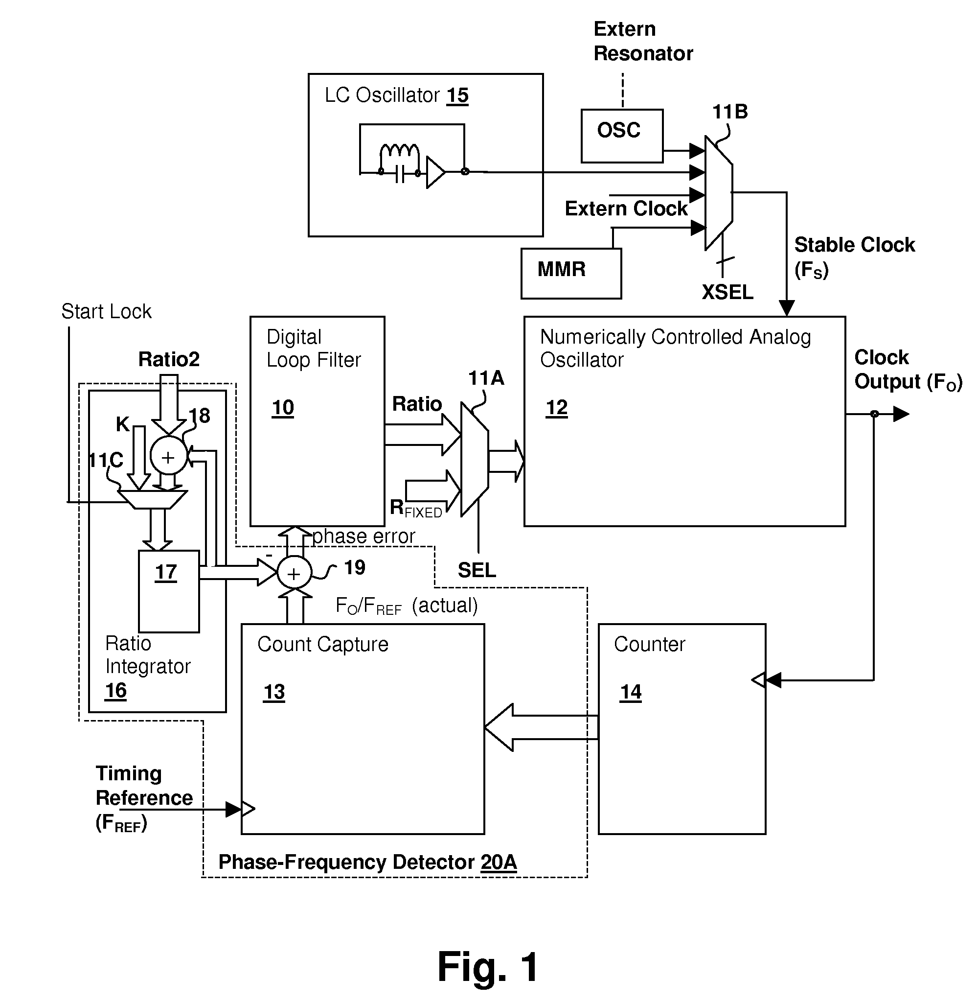
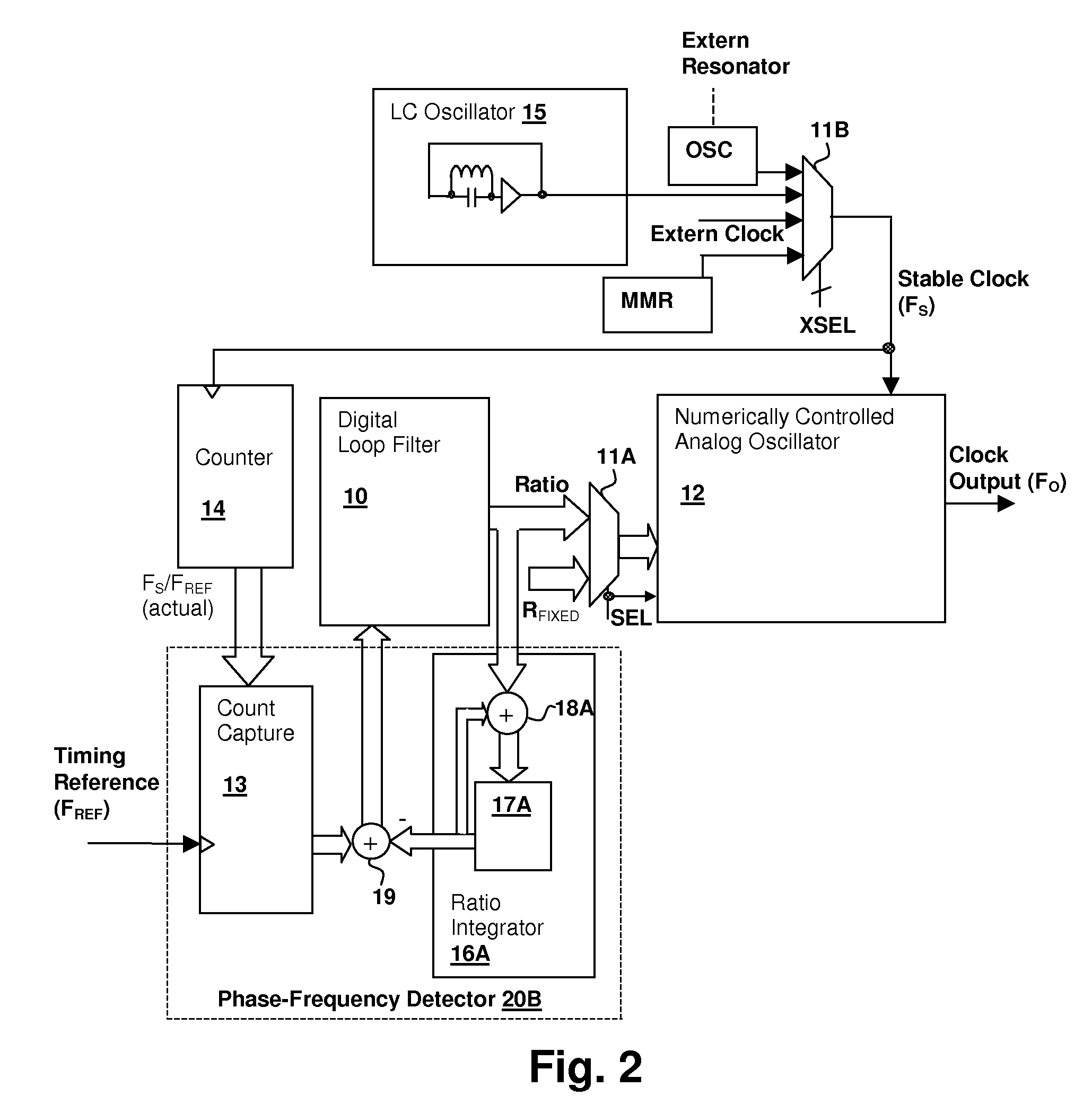
[0021]The present invention encompasses hybrid analog / digital hybrid PLL circuits and methods of operation for providing a low-jitter clock output from a timing reference that may have a large amount of jitter. A digital PLL is used to provide a ratiometric frequency control number that is then provided to a numerically-controlled analog oscillator that generates a low jitter clock output. Feedback may be provided from the clock output to the digital PLL in a feedback configuration, or the numerically controlled oscillator may be operated in a feed-forward configuration.

[0022]Referring now to FIG. 1, an exemplary hybrid analog / digital PLL circuit in accordance with an embodiment of the invention is shown. The depicted embodiment is a feedback configuration of the hybrid analog / digital PLL, with feedback provided from the low-jitter Clock Output signal to a phase-frequency detector 20A that compares the frequency of the Clock Output signal to an expected count value determined from a...


PUM


Abstract

A hybrid analog / digital phase-lock loop for low-jitter synchronization provides a mechanism for generating a low-jitter clock from a timing reference that has a high jitter level. A numerically-controlled analog oscillator provides a clock output and has an input for receiving a rational number. The rational number represents a ratio between the frequency of the clock output and the frequency of another stable clock provided to the circuit. A counter divides the frequency of either the clock output or the stable clock, providing feedback or feed-forward control of the analog oscillator, respectively. The circuit also includes a digital phase-frequency detector for detecting an on-going phase-frequency difference between an input timing reference and an output of the divider and a digital loop filter for filtering the output of the phase-frequency detector to provide the rational number that controls the frequency of the numerically-controlled analog oscillator.

Description

CROSS-REFERENCE TO RELATED APPLICATIONS[0001]This application is related to U.S. provisional application Ser. No. 60 / 826,757, filed Sep. 25, 2006 and from which it claims benefits under 35 U.S.C. §119(e).BACKGROUND OF THE INVENTION[0002]1. Field of the Invention[0003]The present invention relates generally to audio / video (AV) systems, and more specifically, to a synchronizing loop for providing a low-jitter synchronized clock signal.[0004]2. Background of the Invention[0005]Digital audio systems are prevalent in the areas of home entertainment, professional production of multimedia and computer reproduction and generation of multimedia sources. Increasingly, digital audio data is transported from sub-system to sub-system and device to device in both consumer and professional installations and the data is generally provided with, or has embedded, a timing reference that has too much jitter to act as a stable sample clock reference. Furthermore, the timing information may be provided ...

Claims


Application Information

Patent Timeline
Patent Type & Authority Patents(United States)
IPC IPC(8): H03D3/24
CPCH03L7/07H03L7/1976
Inventor MELANSON, JOHN L.YOU, ZHONGWOODFORD, SCOTT ALLANGREEN, STEVEN RANDALL
Owner CIRRUS LOGIC INC
Why Eureka
Try Eureka