Self-propelled snow remover

a self-propelled, snow removal technology, applied in the direction of vehicle position/course/altitude control, process and machine control, instruments, etc., can solve the problems of affecting the operation of affecting the speed of snow removal, etc., to achieve the effect of rapid resumed snow removal, enhanced ability to turn the snow removal machine, and rapid resumption of snow removal

Active Publication Date: 2010-03-23
HONDA MOTOR CO LTD
View PDF12 Cites 13 Cited by
  • Summary
  • Abstract
  • Description
  • Claims
  • Application Information

AI Technical Summary

Benefits of technology

[0009]Therefore, when the steering members are turned, the snow-removing implement can be raised by the lift drive mechanism in conjunction with the operation of the steering members. In other words, the snow-removing implement can be automatically raised to a relatively high position when the self-propelled snow remover is in a turn. Accordingly, since accumulated snow does not interfere with turning, the ability to turn the snow remover during snow removal can be enhanced.
[0010]Afterwards, when the turning operation of the steering members is stopped, the snow-removing implement can be lowered by the lift drive mechanism in conjunction with the completion of the turn operation. In other words, the snow-removing implement can be automatically lowered to a low position when the snow remover has completed the turn. Snow removal can therefore be rapidly resumed.
[0011]The snow-removing implement can thus be automatically raised and lowered in accordance with the operation of the steering members. There is no need for the snow-removing implement to be raised and lowered manually each time the operator causes the snow remover to turn back and resume a forward movement. The burden on the operator can therefore be alleviated even further.

Problems solved by technology

Using human power to vary the height of the auger in this manner places a large burden on the operator.
When the snow remover is turned in this state, accumulated snow interferes with turning depending on the state of snow accumulated around the snow remover.

Method used


Image

  • Self-propelled snow remover
  • Self-propelled snow remover
  • Self-propelled snow remover

Examples


Embodiment Construction

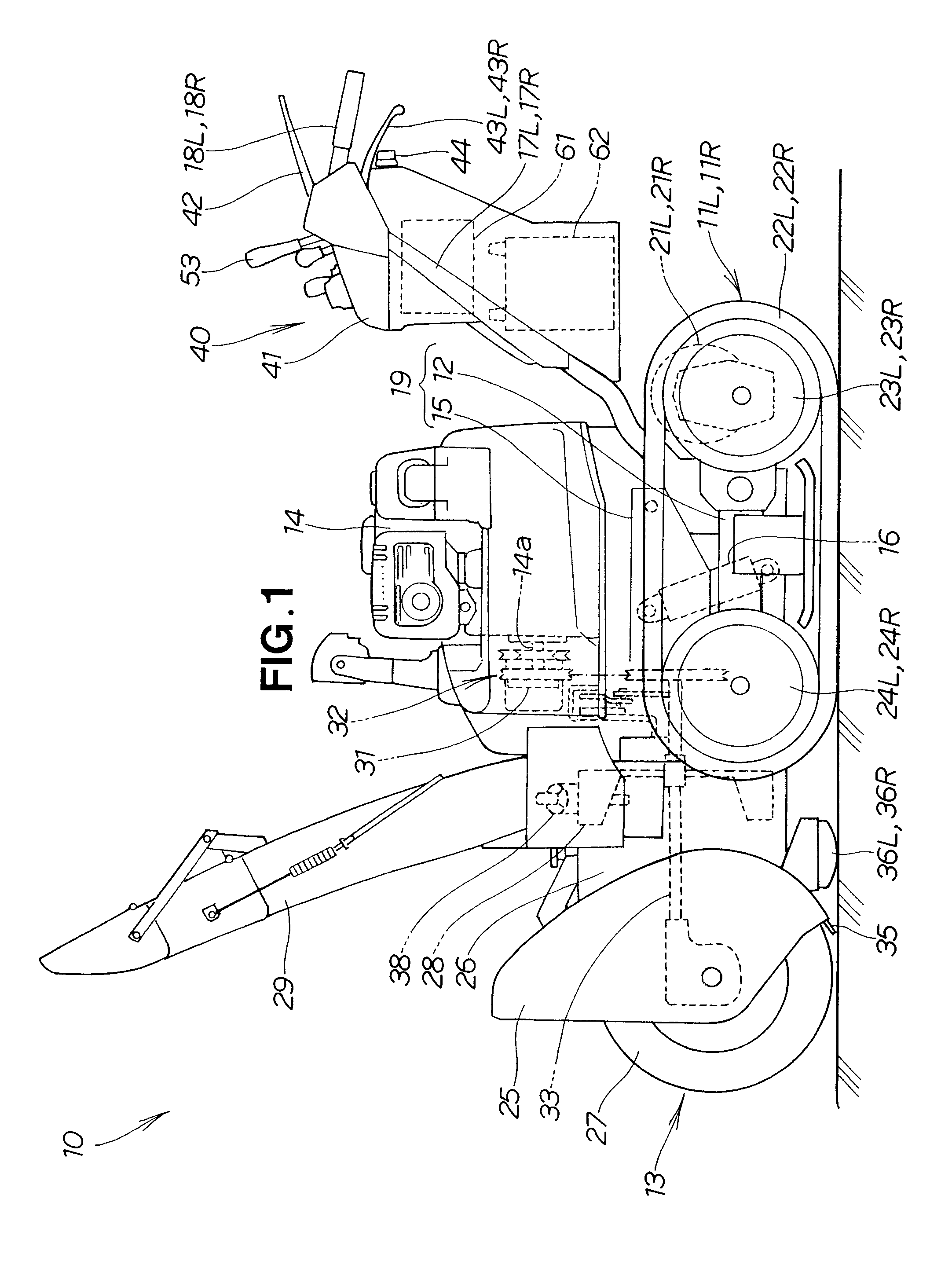
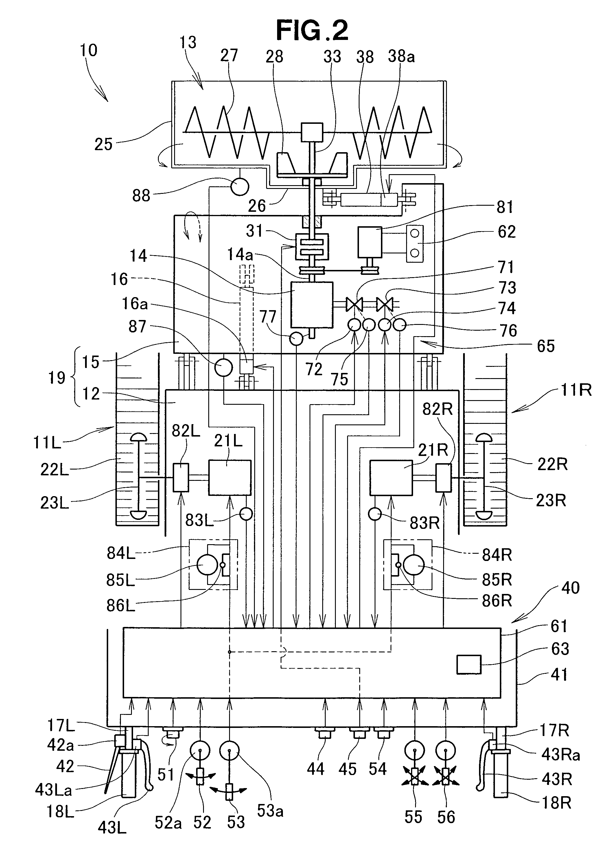
[0029]As shown in FIGS. 1 and 2, the self-propelled snow remover 10 is composed of left and right travel units 11L and 11R, left and right electric motors 21L and 21R for driving the travel units 11L and 11R, an auger-type snow-removing implement 13, an engine 14 for driving the snow-removing implement 13, and a machine body 19. This self-propelled snow remover 10 is referred to as a self-propelled auger-type snow remover. The self-propelled snow remover 10 hereinafter will be referred to simply as the snow remover 10. The snow-removing implement 13 will be referred to simply as the implement 13.

[0030]The machine body 19 is composed of a travel frame 12 and a vehicle body frame 15 attached to the travel frame 12 so as to be able to swing vertically about the back end portion thereof. This machine body 19 is provided with a lift drive mechanism 16 for lifting and lowering the front portion of the vehicle body frame 15 in relation to the travel frame 12.

[0031]The lift drive mechanism ...


PUM


Abstract

A self-propelled snow remover has a machine body, travel units mounted on the machine body to undergo turning movement and linear movement, and at least one steering member mounted to the machine body and operable to turn the travel units. A snow-removing implement is mounted to the machine body to undergo lifting, lowering and rolling movements relative to the machine body. A lift drive mechanism lifts and lowers the snow-removing implement. A control unit controls the lift drive mechanism by issuing a lift drive instruction to the lift drive mechanism so as to automatically lift the snow-removing implement when a steering condition in which the steering member is turned is determined to be satisfied, and by issuing a lowering drive instruction to the lift drive mechanism so as to automatically lower the snow-removing implement when the steering condition is determined to be no longer satisfied.

Description

FIELD OF THE INVENTION[0001]The present invention relates to a snow remover which is self-propelled and has a travel device and a snow-removing implement.BACKGROUND OF THE INVENTION[0002]In some self-propelled snow removers, a snow-removing implement is attached to a machine body so as to be capable of lifting, lowering, and rolling, and a travel unit is provided to the machine body. The snow-removing implement is composed of an auger, for example. In a snow remover provided with an auger, a system is adopted whereby the height of the auger is varied according to snow removal circumstances. Elevating the lower surface of the auger when the snow remover is moving enables more efficient travel. On the other hand, lowering the lower surface of the auger during snow removal enables more efficient snow removal. Furthermore, it is often the case that the height of the auger is varied in conjunction with irregularities in the road surface during snow removal. Using human power to vary the ...

Claims


Application Information

Patent Timeline
Patent Type & Authority Patents(United States)
IPC IPC(8): E02F5/02E01H5/09
CPCE01H5/04
Inventor WAKITANI, TSUTOMUKAWAKAMI, TOSHIAKI
Owner HONDA MOTOR CO LTD
Why Eureka
Try Eureka