Adhesive bandage carrier and bandage dispensing assembly therefor

a technology of adhesive bandages and carrier, which is applied in the direction of bandages, instruments, apparatus for dispensing discrete objects, etc., can solve the problems of wasting valuable time, wasting valuable time, and wasting paper and other materials in extraordinary amounts, so as to achieve convenient use and storage, fast and convenient dispense, the effect of cleaning and saving tim

Active Publication Date: 2010-03-23
DUKE ENTERPRISES
View PDF2 Cites 25 Cited by
  • Summary
  • Abstract
  • Description
  • Claims
  • Application Information

AI Technical Summary

Benefits of technology

[0005]Accordingly, a primary objective of the device of the present invention is to provide an improved adhesive bandage carrier and an assembly for dispensing such adhesive bandage carrier that results in a faster, cleaner and more economical way to dispense adhesive bandages of present manufacture. It is another object of the present invention to provide such a carrier and dispenser assembly such that the carrier and assembly can be used in an institutional setting, in a home setting, or in any other setting that would require care pertaining to the application for an adhesive bandage. It is still another object of the present invention to provide such a carrier and dispensing assembly that can be used by persons of any age or disability and can allow for single-handed receipt of an adhesive bandage in such a way that the bandage is received in a ready-to-be-applied manner. It is yet another object of the present invention to provide such a carrier and dispensing assembly that is available to accommodate different size bandages and that also allows for refilling of the dispensing assembly when bandages are depleted. It is still another object of the present invention to provide such a carrier and dispensing assembly that is reasonable in cost so that the device is economical for use in all settings. It is still another object of the present invention to provide such a carrier and dispensing assembly that can be fabricated as a mechanically-operated unit or as an electrically-operated unit, and that can be fabricated to actuate the dispensing of the bandage by mechanical means or by electronic or other sensing means. It is yet another object of the present invention to provide such a carrier and dispensing assembly that is convenient for use and storage in the home or elsewhere.

Problems solved by technology

In the experience of this inventor, time is wasted while searching this envelope or packaging for the proper end to open.
Once done, the user must spend time peeling away the adhesive coverings, creating wasted and loose material at each step in the process.
In the medical setting, the old method described above wastes valuable time and an extraordinary amount of wasted paper and other material.
In emergency settings, this is clearly unacceptable.
In addition to wasted time and material, extra handling of the bandage increases the risk of infection for the patient through extra contact with the bandage and prolonged wound exposure.

Method used


Image

  • Adhesive bandage carrier and bandage dispensing assembly therefor
  • Adhesive bandage carrier and bandage dispensing assembly therefor
  • Adhesive bandage carrier and bandage dispensing assembly therefor

Examples


first embodiment

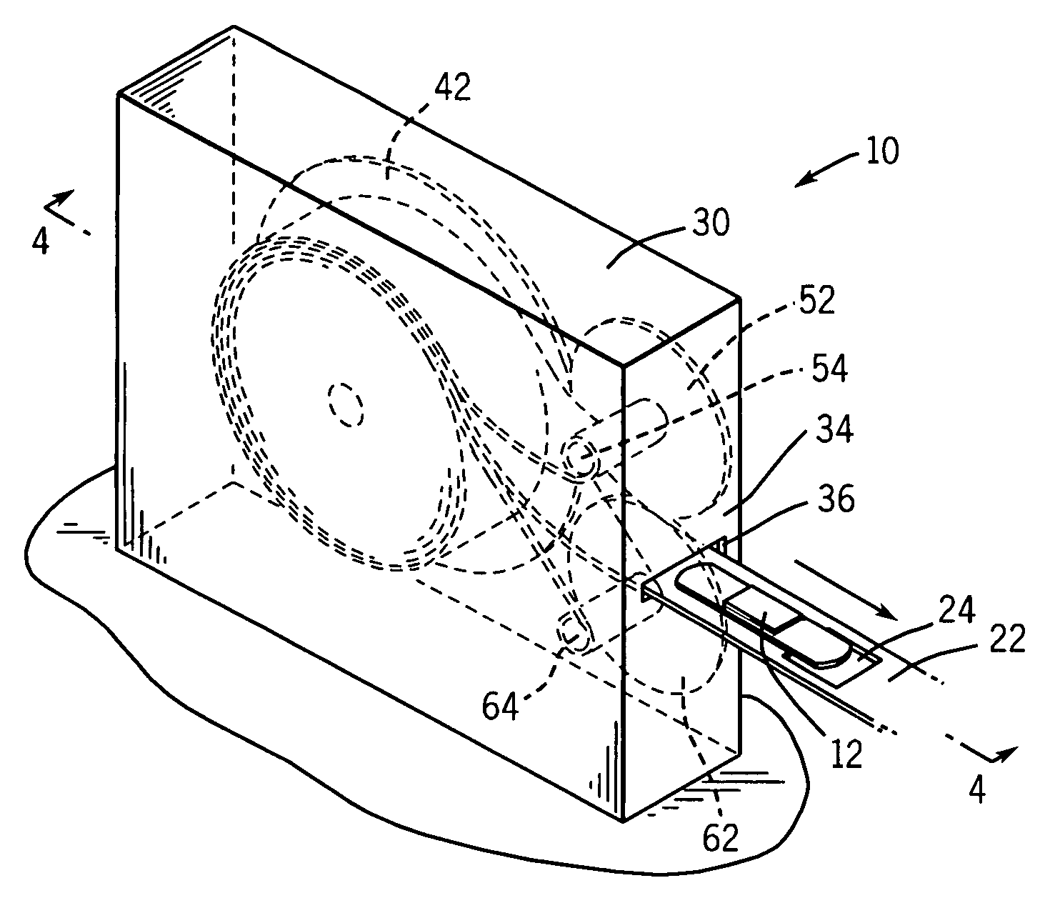
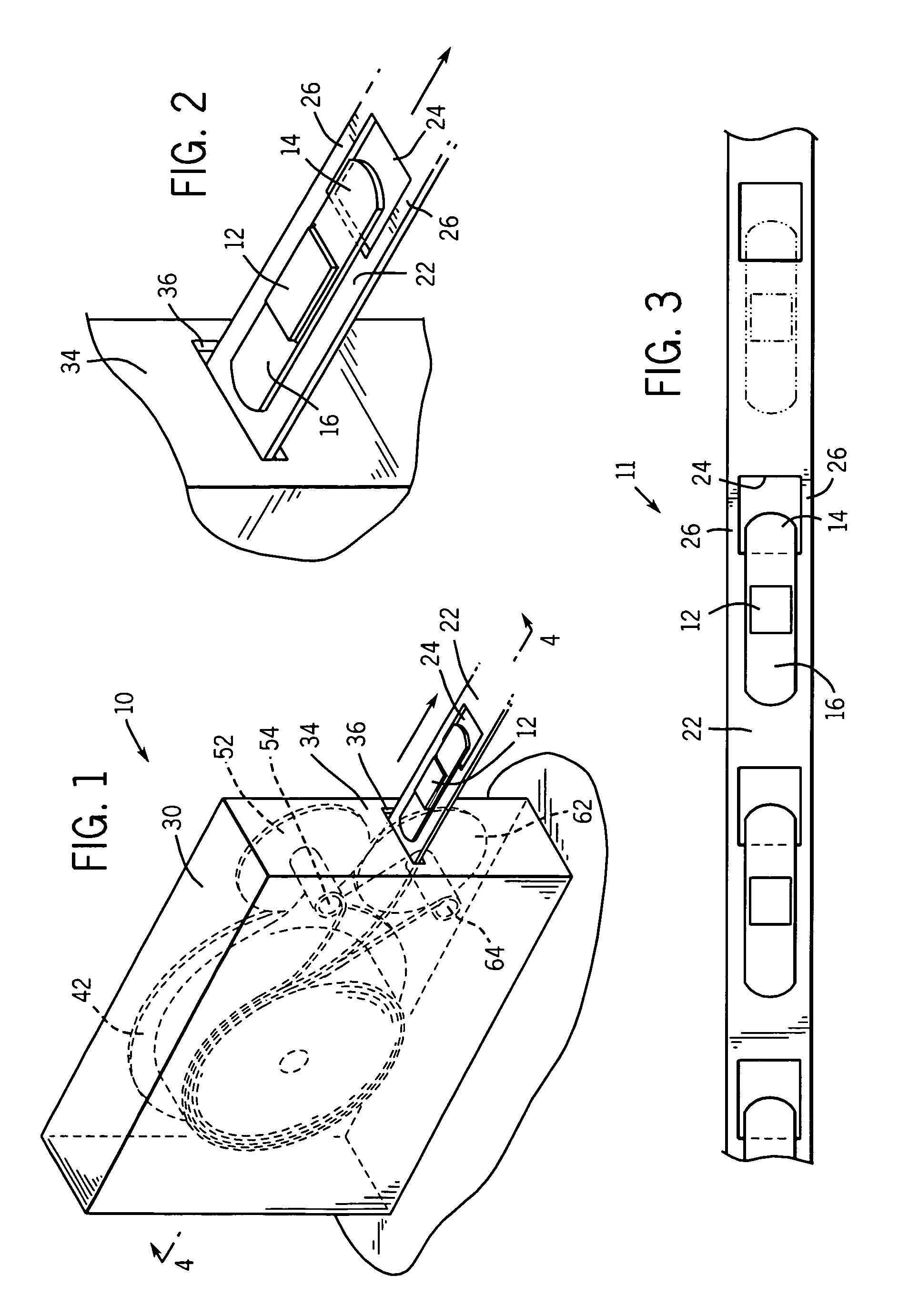
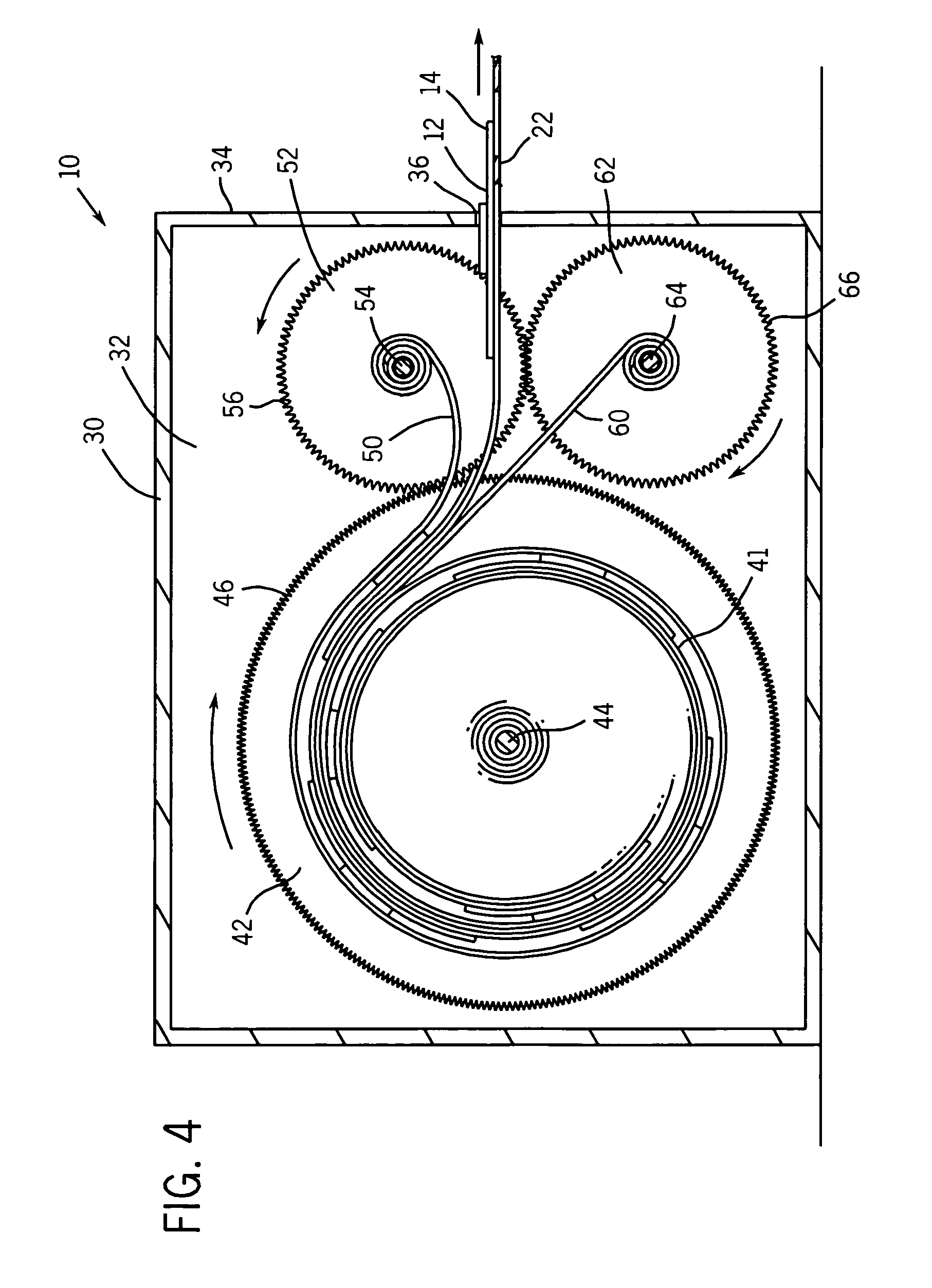
[0025]Referring again to FIGS. 1 and 4 in particular, it will be seen that the internal area 32 of the dispenser assembly 10 includes, in the first embodiment, a first rotational means in the form of a first gear 42, a second rotational means in the form of a second gear 52, and third rotational means in the form of a third gear 62. It is to be understood that this configuration could be varied and the rotational means and gear drive arrangement could be configured differently without deviating from the scope of this invention. The first rotational means is intended to be a “feed” means for delivering a roll 41 of adhesive bandage carrier 11 from within the container 30 to its outside. The second and third rotational means are each intended to be a “take-up” means for other material that overlays the adhesive bandage carrier 11, such take-up to be accomplished within the container 30.

[0026]In the first preferred embodiment of the assembly 10, it is to be understood that the first ro...

second embodiment

[0033]The internal area 132 of the dispenser assembly 100 of the second preferred embodiment includes a first gear 152 and a second gear 162. It is to be understood that this configuration could be varied and the gear drive could be configured differently without deviating from the scope of this invention. As shown in FIG. 9, it will be seen that a third pin 144 is used as the feeder for the bandage carrier 11 where a pre-wound roll 141 of the bandage carrier 11 is rotatably and removably pre-wrapped about the pin 144. Thus, when the second gear 162 is rotated in the clockwise direction as viewed in FIG. 9 by the motor 170, the bandage carrier 11 is pulled and the bandage carrier 11 unwinds itself from the pin 144. The second gear 162 has a plurality of teeth 166 defined about its perimeter. As shown in this particular embodiment, the teeth 166 of the second gear 162 mesh with gear teeth 156 of the first gear 152, the first gear 152 also including a centrally-disposed pin 154. Thoug...

fourth embodiment

[0035]Referring now to FIG. 11, it illustrates a fourth preferred embodiment of a dispenser assembly generally identified 300, that is used to dispense bandage carrier in accordance with the present invention. In general, the dispenser assembly 300 includes a dispenser enclosure 330 that defines an interior area 332. The dispenser enclosure 330 includes a face 334 having an aperture 336 defined in it. As shown, the opening 336 that is defined within the face 334 of the container 330 is a generally elongated and rectangular opening. Again, the reason for that configuration is that the opening 336 must be able to allow the bandage carrier 11 to freely pass through it. The internal area 332 of the dispenser assembly 300 includes, in the fourth embodiment, a first gear 352 and a second gear 362. It is to be understood that this configuration could be varied and the gear drive could be configured differently without deviating from the scope of this invention. As shown in FIG. 11, it will...


PUM


Abstract

A dispenser assembly includes a housing having a face and an aperture that allows adhesive bandage carrier to pass through it. The adhesive bandage carrier comprises a longitudinally-extending carrier strip having a plurality of longitudinally-disposed adhesive bandages removably secured to an underlying carrier strip. The bandages are located at pre-determined and equally-spaced intervals along the strip. At the same intervals, the strip includes a plurality of apertures. A first edge of the bandage overlays a portion of an aperture such that the first edge can be easily grasped when the bandage is dispensed. The dispenser assembly also includes a number of rotational elements that serve as either “feed” mechanisms for delivering a roll of adhesive bandage carrier from within the container or “take-up” mechanisms for accumulating protective material that overlays the bandage carrier. Different embodiments of the assembly afford mechanical and electrical actuation of the dispensing assembly.

Description

FIELD OF THE INVENTION[0001]The present invention relates generally to adhesive tapes, adhesive bandages, and to assemblies for dispensing such tapes and bandages. More specifically, it relates to an adhesive bandage carrier that has an aperture defined within the carrier such that a leading edge of the bandage can be easily grasped by the user and the bandage removed from the carrier. It also relates to an assembly for dispensing adhesive bandages from the carrier.BACKGROUND OF THE INVENTION[0002]In the area of adhesive bandages that are used to cover wounds and the like, it is known that application of the bandage begins with removing the bandage from a sterile envelope of some sort. Removal of the bandage typically requires the user to grasp the sterile envelope in one hand and then tear the envelope open with the other hand, clearly a two-handed operation. Once removed from the envelope, the bandage typically includes other coverings for the adhesive portion of the bandage, agai...

Claims


Application Information

Patent Timeline
Patent Type & Authority Patents(United States)
IPC IPC(8): A61F13/00G07F11/66G07F11/68
CPCA61F15/001A61F15/002
Inventor WENDORF, JOHN W.
Owner DUKE ENTERPRISES
Why Eureka
Try Eureka