Optical lens system for taking image

a technology of optical lens and image, applied in the field of optical lens system for taking image, can solve the problems of reducing the degree of freedom available, unable to meet the requirement of miniaturization, and a relative large mechanical structure, so as to reduce the volume of the optical lens system, improve image quality

Active Publication Date: 2010-03-23
LARGAN PRECISION
View PDF2 Cites 50 Cited by
  • Summary
  • Abstract
  • Description
  • Claims
  • Application Information

AI Technical Summary

Benefits of technology

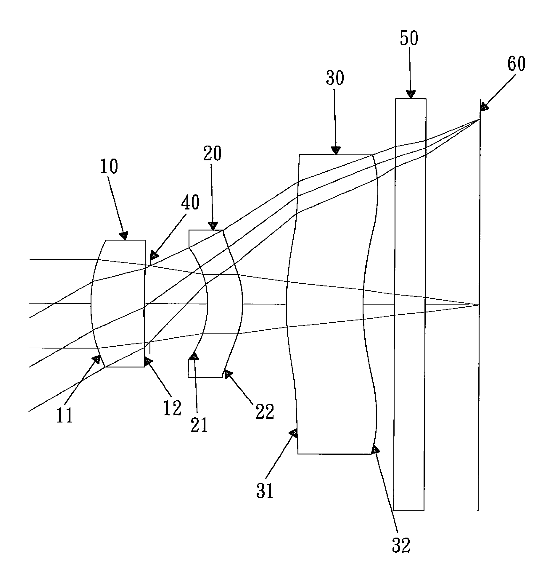
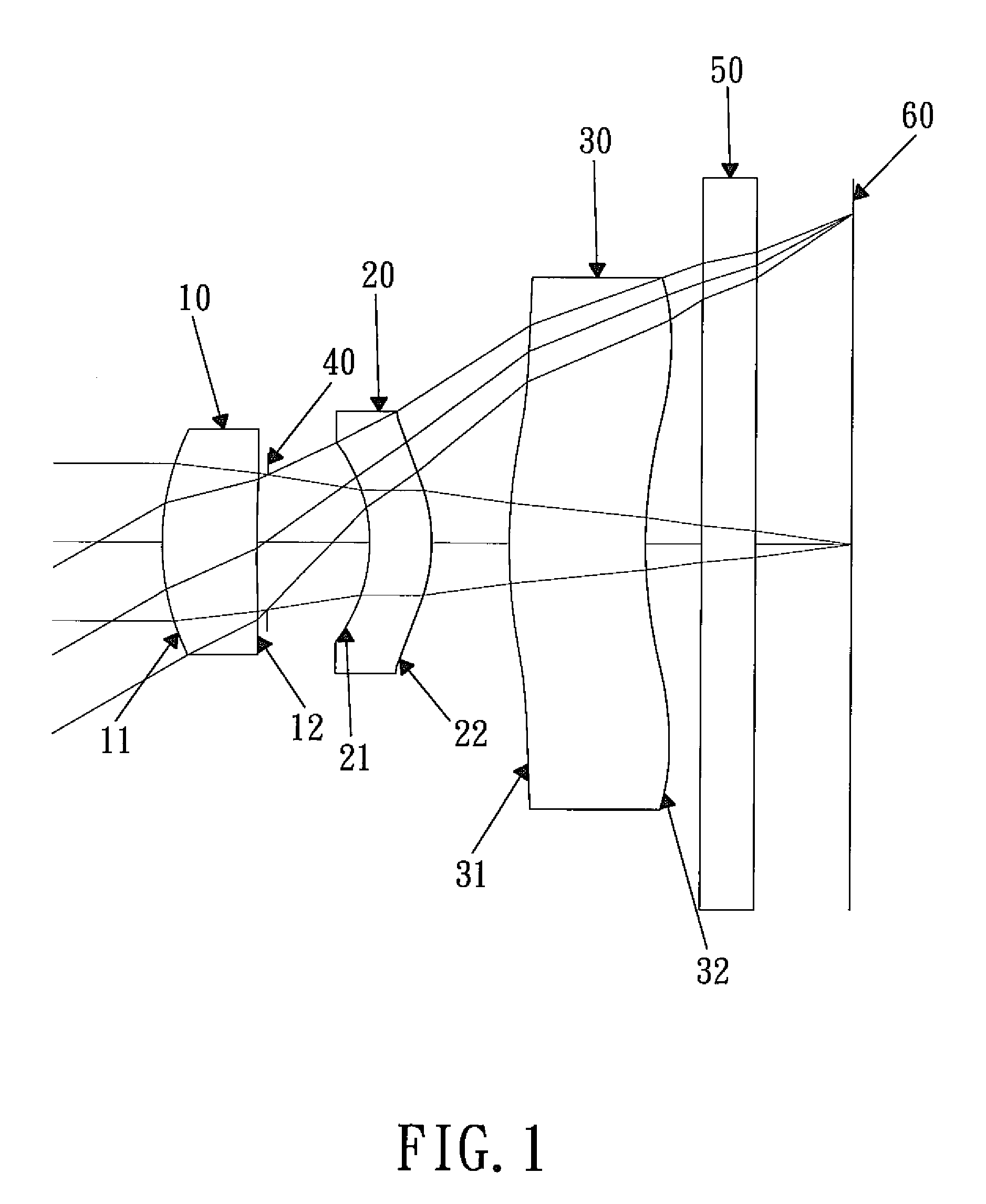
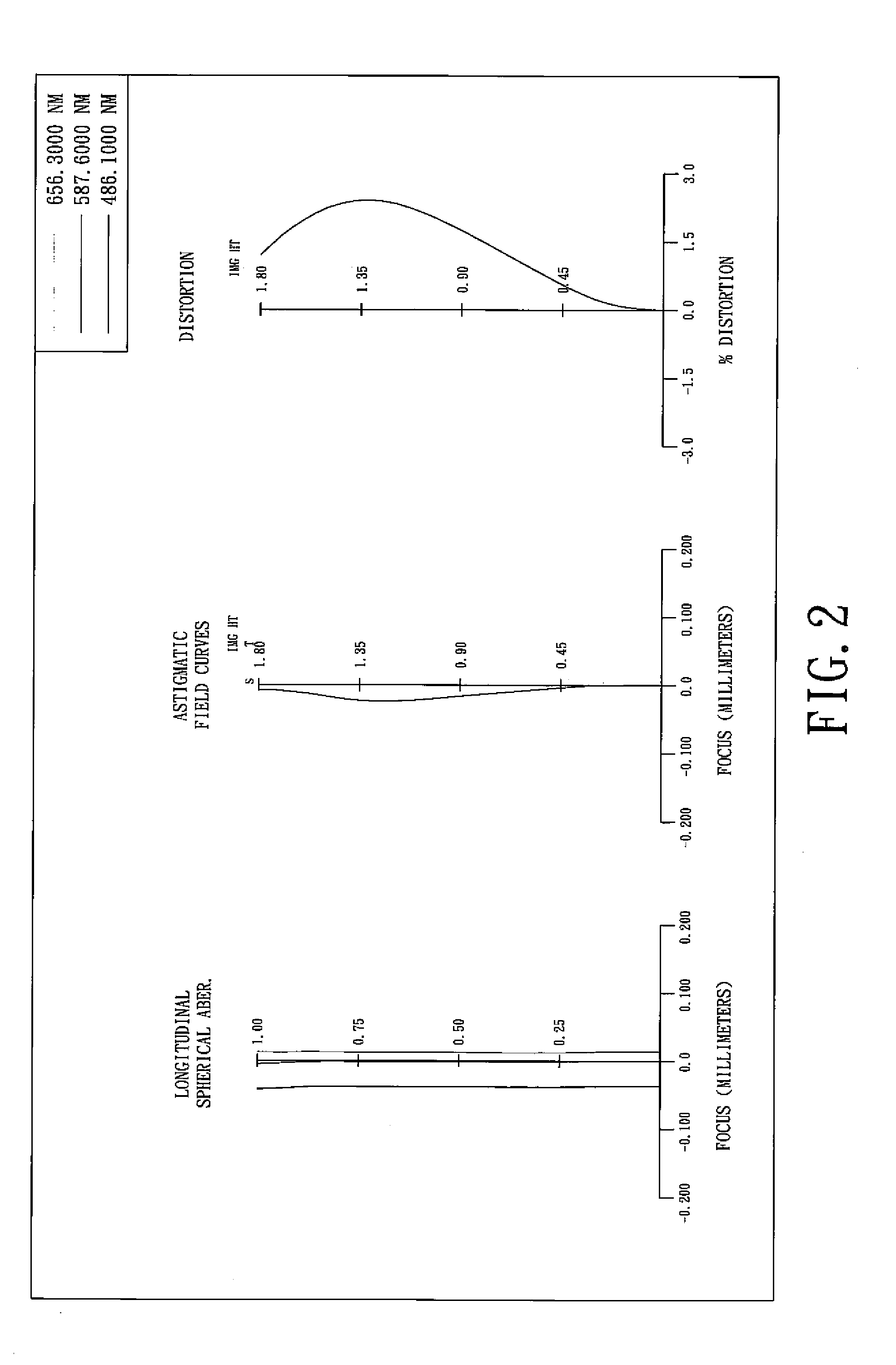
[0009]The primary objective of the present invention is to improve image quality, and effectively reduce the volume of the optical lens system while considering the ease of manufacture of the lens elements. The present invention provides a whole new three-lens type optical lens system.

Problems solved by technology

However, the third lens element of the above patent is positive in such a manner that the principal point is close to the image side of the system, so the back focal length is relatively long, which results in a relatively large mechanical structure.
As a result, the requirement of miniaturization can not be satisfied.
The use of the spherical lens element reduces the degrees of freedom available for correcting the off-axis aberration of the optical lens system, making it more difficult to control image quality.

Method used


Image

  • Optical lens system for taking image
  • Optical lens system for taking image
  • Optical lens system for taking image

Examples


first embodiment

[0050]The equation for the aspheric surface profiles of the first embodiment is expressed as follows:

[0051]X⁡(Y)=(Y2 / R) / (1+sqrt⁡(1-(1+k)*(Y / R)2))+∑i⁢⁢(Ai)*(Yi)

[0052]wherein:

[0053]X: the height of a point on the aspheric lens surface at a distance Y from the optical axis, relative to the tangential plane at the aspheric surface vertex;

[0054]Y: the distance from the point on the curve of the aspheric surface to the optical axis;

[0055]k: the conic coefficient;

[0056]Ai: the aspheric surface coefficient of order i.

[0057]In the first embodiment of the present optical lens system for taking image, the focal length of the optical lens system for taking image is f, the focal length of the first lens element is f1, the focal length of the second lens element is f2, the focal length of the third lens element is f3, and they satisfy the relations:

f=3.11 mm;

f / f1=1.12;

f / f2=−0.12;

f / f3=−0.05.

[0058]In the first embodiment of the present optical lens system for taking image, the refractive index of t...

second embodiment

[0076]In the present optical lens system for taking image, the focal length of the optical lens system for taking image is f, the focal length of the first lens element is f1, the focal length of the second lens element is f2, the focal length of the third lens element is f3, and they satisfy the relations:

f=2.88 mm;

f / f1=1.33;

f / f2=−0.32;

f / f3=−0.10.

[0077]In the second embodiment of the present optical lens system for taking image, the refractive index of the first lens element is N1, and it satisfies the relation: N1=1.543.

[0078]In the second embodiment of the present optical lens system for taking image, the refractive index of the second lens element is N2 and it satisfies the relation: N2=1.632.

[0079]In the second embodiment of the present optical lens system for taking image, the refractive index of the third lens element is N3, and it satisfies the relation: N3=1.543.

[0080]In the second embodiment of the present optical lens system for taking image, the Abbe number of the first ...


PUM


Abstract

An optical lens system for taking image consisting of three lens elements with refractive power, in order from the object side to the image side: a meniscus first lens element with positive refractive power having a convex object-side surface; an aperture stop; a meniscus plastic second lens element with negative refractive power having a convex image-side surface, and the object-side surface and the image-side surface of the second lens element being both aspheric, the Abbe number of the second lens element being V2, and it satisfying the relation: V2>40; a meniscus plastic third lens element with negative refractive power having a convex object-side surface, the object-side surface and the image-side surface of the third lens element being both aspheric, an Abbe number of the third lens element being V3, and it satisfying the relation: V3>40.

Description

BACKGROUND OF THE INVENTION[0001]1. Field of the Invention[0002]The present invention relates to an optical lens system for taking image, and more particularly to a miniaturized optical lens system for taking image used in a digital camera.[0003]2. Description of the Prior Art[0004]In recent years, with the popularity of the mobile phone camera, the optical lens system for taking image has become thinner and thinner, and the electronic imaging sensor of a general digital camera is typically a CCD (Charge Coupled Device) or CMOS (Complementary Metal Oxide Semiconductor) sensor. Due to advances in semiconductor manufacturing, the pixel size of sensors has been reduced continuously, and miniaturized optical lens systems for taking image have increasingly higher resolution. Therefore, there's increasing demand for image quality.[0005]A conventional mobile phone camera described usually consists of three lens elements: from the object side to the image side: a first lens element with pos...

Claims


Application Information

Patent Timeline
Patent Type & Authority Patents(United States)
IPC IPC(8): G02B9/12
CPCG02B13/18
Inventor TANG, HSIANG-CHI
Owner LARGAN PRECISION
Why Eureka
Try Eureka