
Wireless device and wireless network system

a wireless network and terminal technology, applied in the direction of wireless communication, transmission monitoring, modulation, etc., can solve the problems of data communication being affected by, electric wave interference between the devices appearing, and not described a specific method for analyzing the measurement, so as to achieve optimal communication channels

Inactive Publication Date: 2010-03-23
SOCIONEXT INC
View PDF12 Cites 1 Cited by
  • Summary
  • Abstract
  • Description
  • Claims
  • Application Information

AI Technical Summary

Benefits of technology

This approach ensures that communication channels are selected without degrading the state of ongoing communications, prioritizing important data transmissions and minimizing wave interference, thereby maintaining optimal communication states across the network.

Problems solved by technology

With the widespread use of wireless communication devices, the problem of electric wave interference between the devices has been appearing.
However, the prior art technology mentioned above has not described a specific method for analyzing the measurement results at the base station.
For example, there is the possibility that, with the communication channel newly selected by the base station, the wireless terminal which has performed important data communication may be affected by wave interference and the data communication may be inhibited thereby.
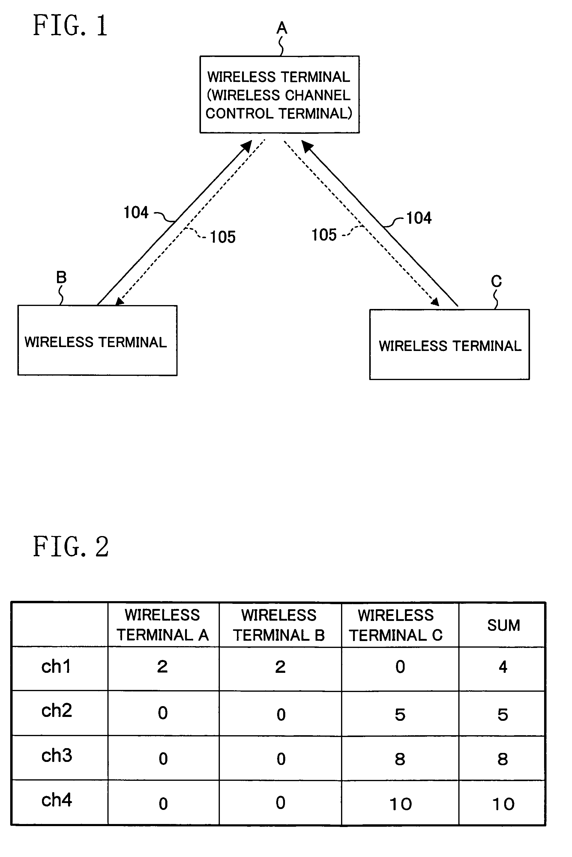
At this time, if it is assumed that the wireless terminals A and B are currently performing important data communication therebetween and the wireless terminal C is performing no data communication, the problem occurs that the changing of the communication channel from the channel ch4 to the channel ch1 based on the measurement results from the wireless terminal C causes trouble in the data communication between the wireless terminals A and B that has been optimal thus far.
Thus, the changing of the communication channel based only on the results of individual measurement at any of the wireless terminals may occasionally cause trouble in the communication of another wireless terminal.

Method used


Image

  • Wireless device and wireless network system
  • Wireless device and wireless network system
  • Wireless device and wireless network system

Examples


embodiment 1

[0050]A description will be given first to a first embodiment of the present invention.

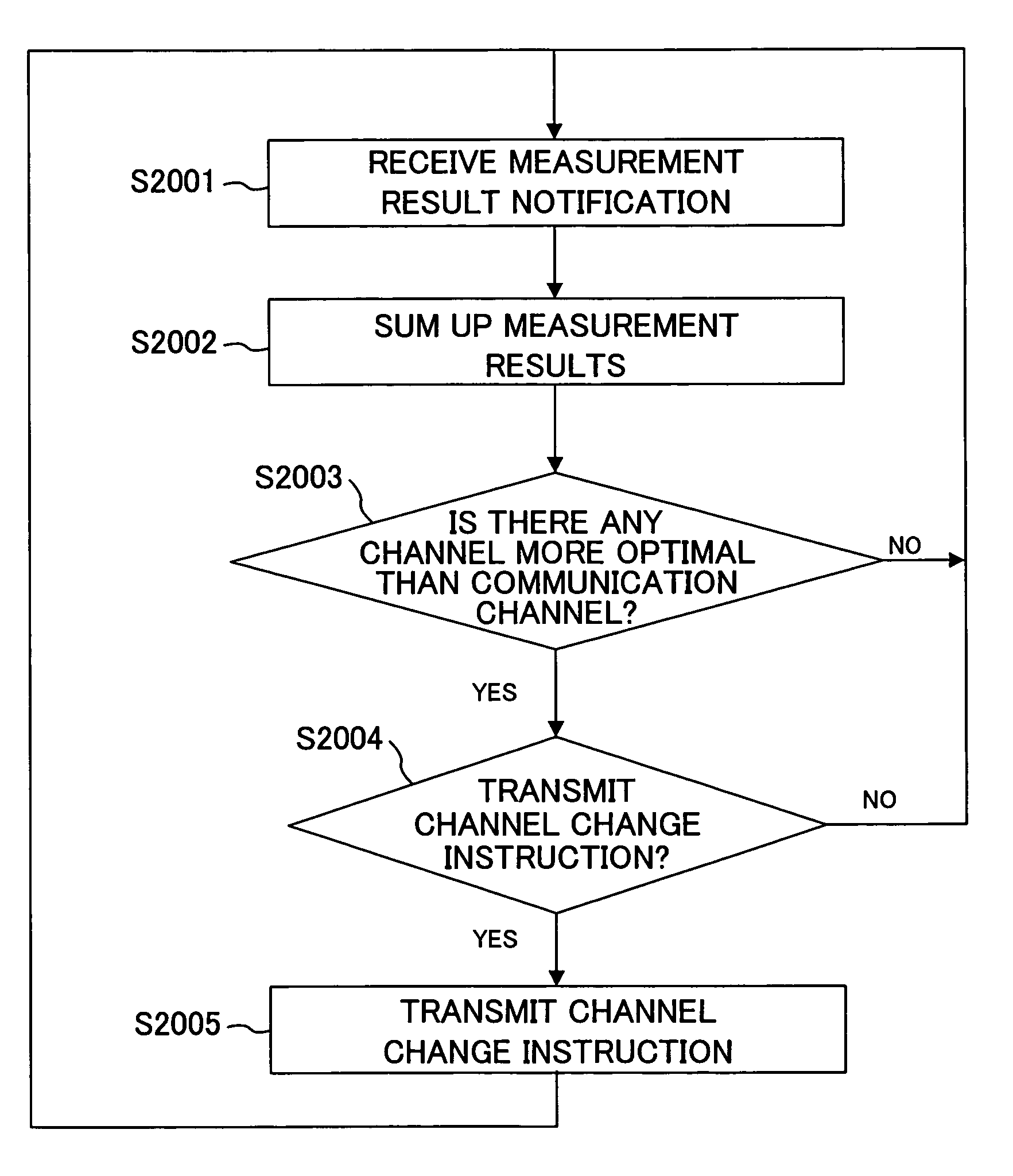
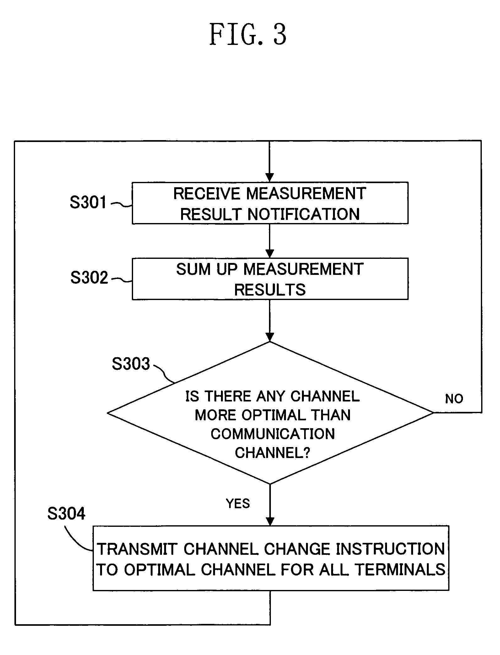
[0051]FIG. 1 shows a wireless network structure composed of one wireless channel control terminal A and two wireless terminals B and C. Each of the two wireless terminals B and C measures the states of use of usable wireless channels each indicating whether or not the communication state is optimal and notifies the wireless channel control terminal A of the results of measurement as a measurement result notification 104.

[0052]Of the wireless terminals (wireless channel control terminals) A, B, and C, the wireless terminal A is different from the other wireless terminals B and C in that it analyzes the results of measuring the states of use of the communication channels at the wireless terminals A, B, and C and determines a more optimal communication channel to which the current communication channel can be changed based on the result of analysis.

[0053]The wireless terminal A functions as the wirel...

embodiment 2

[0064]Referring to FIGS. 5A and 5B, a description will be given next to a second embodiment of the present invention.

[0065]FIG. 5A is a weighting table for setting weights based on various factors at the individual wireless terminals including the wireless terminal (wireless channel control terminal) A. The weighting table is held in the memory region of the communication channel determining unit 202 of the wireless terminal A. As shown in the table of FIG. 5B, the weighting table is reflected on the result of summing up the measurement results from the individual wireless terminals including the wireless terminal A. For example, because the value of the weight set to the wireless terminal A is 3 in FIG. 5A, the measurement results from the wireless terminal A has a weight triple the weight of the measurement result notification 221 from the channel measuring unit 216 of each of the wireless terminals B and C to which the weight having the value of 1 has been set. Accordingly, in th...

embodiment 3

[0069]Referring to FIGS. 6A and 6B, a description will be given next to a third embodiment of the present invention.

[0070]FIG. 6A shows a weighting table based on the presence or absence of a bandwidth guarantee. As a weighting factor, the presence or absence of a bandwidth guarantee (specified weight) given to data communication at each of the wireless terminals A, B, and C is used in the present embodiment. Data communication to which a bandwidth guarantee is given is normally important data communication such as, e.g., image data currently being delivered which has a high need to be protected from wave interference. Accordingly, important data communication in the wireless network can be protected by setting a large weight to each of the measurement results from the wireless terminal performing data communication with a bandwidth guarantee.

[0071]FIG. 6B shows the summing up of the measurement results on which the result of weighting based on the presence or absence of a bandwidth...


PUM


Abstract

When the communication channel is to be changed, a more optimal communication channel is determined by summing up the results of measuring communication states transmitted from individual wireless terminals A, B, and C and making a collective judgment. Weighting coefficients are set to the individual wireless terminals A, B, and C. Values indicating whether or not the respective communication states of the individual wireless terminals are optimal with channels ch1 to ch4 to be used for communication (which are, e.g., 1, 0, 1, 2 with the respective channels ch1, ch2, ch3, and ch4 for the wireless terminal A and larger as the communication states are less optimal) are multiplied by the weight coefficient (the value of 3). The resulting values are summed up on a per-channel basis and the most optimal communication channel (of which the summed value is lowest) is selected. As a result, wave interference with the other wireless terminal is reduced.

Description

CROSS REFERENCE TO RELATED APPLICATION[0001]This Non-provisional application claims priority under 35 U.S.C. § 119(a) on Patent Application No. 2004-381062 filed in Japan on Dec. 28, 2004, the entire contents of which are hereby incorporated by reference.BACKGROUND OF THE INVENTION[0002]The present invention relates to wireless terminals and a wireless communication system in wireless communication which selects a communication channel.[0003]With the widespread use of wireless communication devices, the problem of electric wave interference between the devices has been appearing. As means for circumventing the wave interference, it is possible to measure the states of use of usable wireless channels and use the wireless channels which do not interface with each other.[0004]As disclosed in U.S. Pat. Application Publication No. US 2002 / 0060995 A1, a conventional method for selecting a communication channel in wireless communication measures the states of use of wireless channels at ea...

Claims


Application Information

Patent Timeline
Patent Type & Authority Patents(United States)
IPC IPC(8): H04B17/00H04B15/00H04B7/00H04W72/54H04W72/02
CPCH04W72/02H04W24/10
Inventor MIKAMI, TAROOGAWA, SUGURUNAGAO, AKIFUMIIRIE, MASATAKA
Owner SOCIONEXT INC
Learn More