
Wireless communication device for periodically controlling a carrier wave to establish a good communication state with a communication object

a wireless communication and carrier wave technology, applied in the direction of electromagnetic radiation sensing, near-field systems using receivers, instruments, etc., can solve the problems of lowering the reliability of the antenna device, the power-on-reset function of the wireless tag does not work in some cases properly, and the voltage generated inside the wireless tag becomes gentle. , to achieve the effect of high reliability and good communication sta

Active Publication Date: 2009-04-07
KK TOSHIBA
View PDF31 Cites 2 Cited by
  • Summary
  • Abstract
  • Description
  • Claims
  • Application Information

AI Technical Summary

Benefits of technology

The present invention provides a wireless communication device that can reliably establish a good communication state with a communication object regardless of its status. This is achieved by periodically controlling the carrier wave transmitted from the device to the object in a temporary off manner, allowing for a proper power-on-reset function of the object. Additionally, the carrier wave can be set to a level lower than the threshold temporarily to ensure proper operation of the power-on-reset function of the object in case of failure in the connection between the device and the object.

Problems solved by technology

That is, while an object equipped with a wireless tag passing through between a pair of antenna assembly members, if the wireless tag enters the communication ready area of the antenna device at a relatively low speed, the rise of the voltage generated inside the wireless tag becomes gentle and therefore the power-on-reset function of the wireless tag does not operate properly in some cases.
In these case, the communication between the antenna device and the wireless tag is not established, and therefore the reliability of the antenna device is lowered.
Thus, the switch is operated a number of times while the connection state is on, and therefore the contact point of the switch is caused to labor, thereby shortening the lifetime of the contact point.

Method used

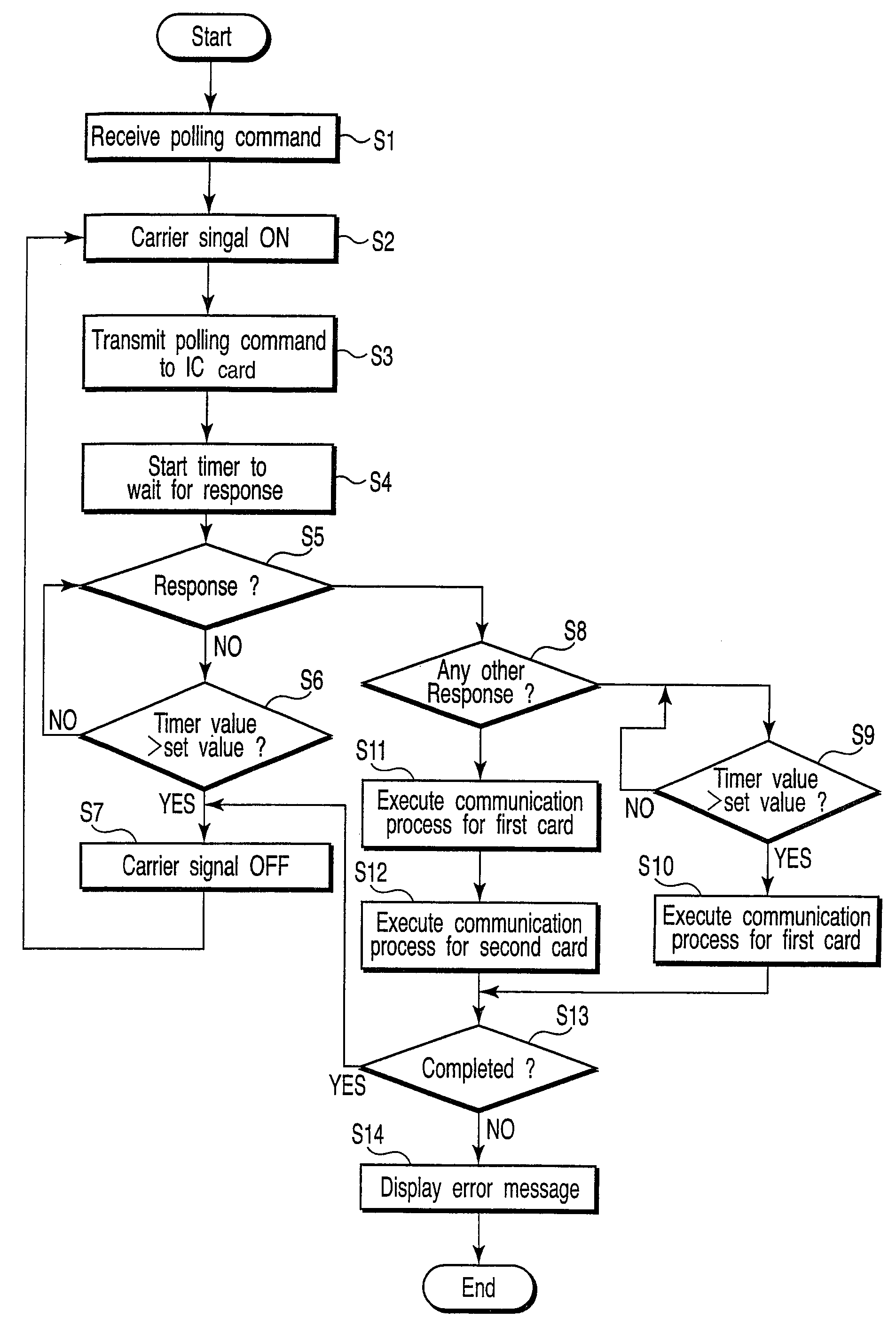
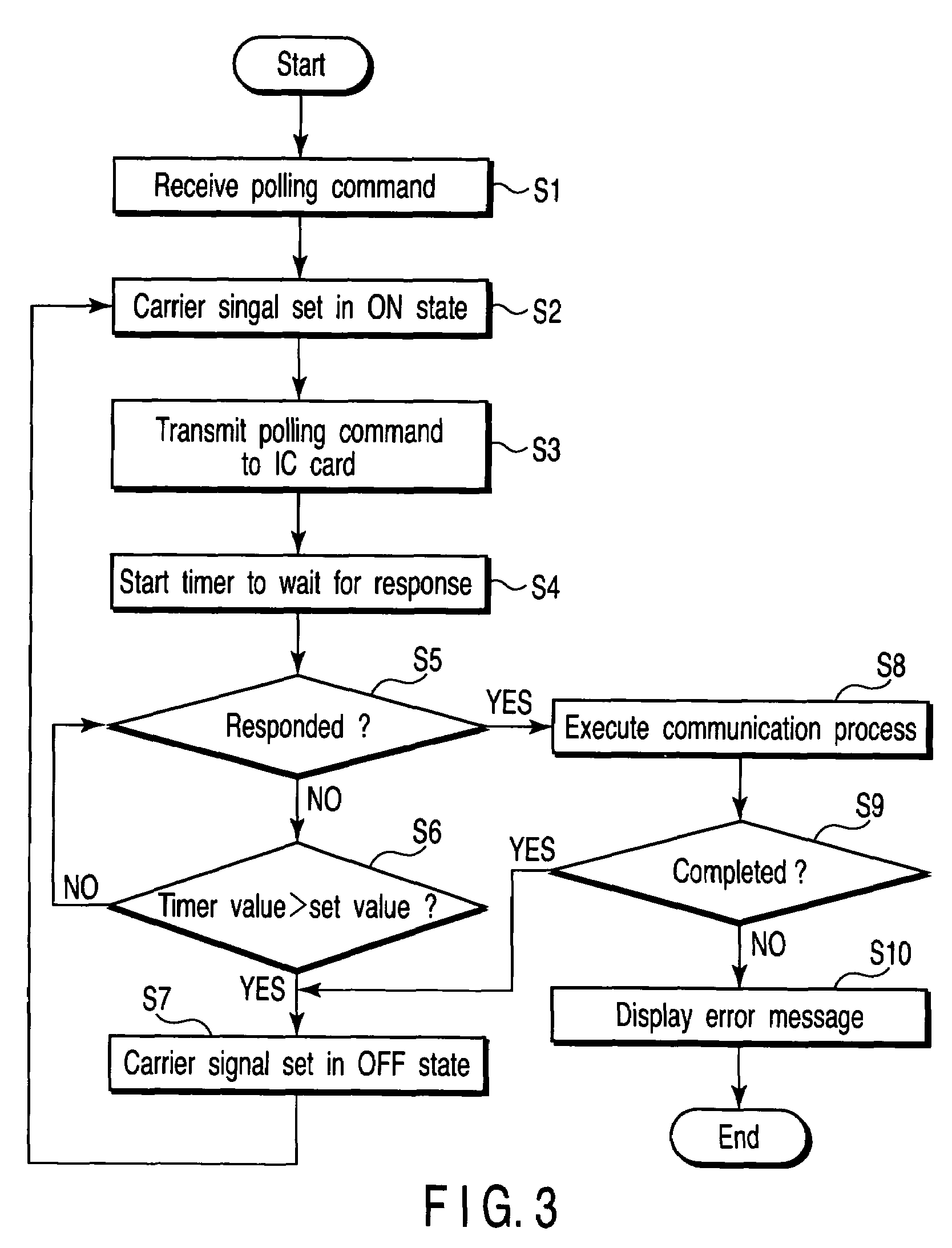

Image

  • Wireless communication device for periodically controlling a carrier wave to establish a good communication state with a communication object
  • Wireless communication device for periodically controlling a carrier wave to establish a good communication state with a communication object
  • Wireless communication device for periodically controlling a carrier wave to establish a good communication state with a communication object

Examples


Embodiment Construction

[0026]Embodiments of the present invention will now be described in detail with reference to accompanying drawings.

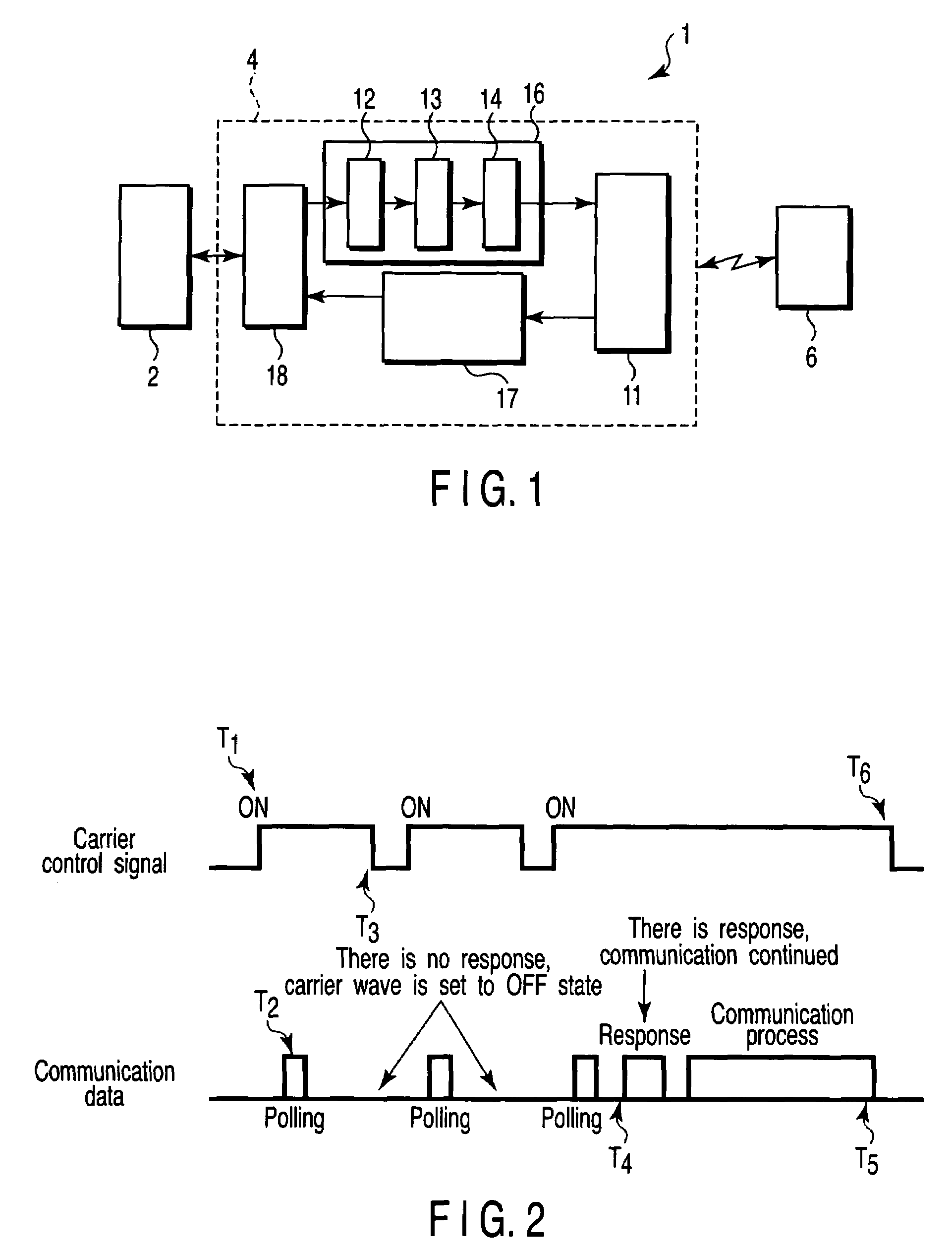
[0027]FIG. 1 is a block diagram schematically showing a structure of a wireless communication device 1 according to the first embodiment of the present invention. As shown in the figure, the wireless communication device 1 includes a host device 2 and a reader / writer 4 that are connected to each other via wire or wirelessly. The feature of this embodiment is that the reader / writer 4 has a single antenna 11.

[0028]The host device 2 of the wireless communication device 1 transmits various types of command data regarding signal transmission to the reader / writer 4, and receives a response result from a non-contact IC card 6 (to be referred to simply as IC card 6 hereinafter), that is, a communication object, via the reader / writer 4.

[0029]The reader / writer 4 includes a single antenna 11 designed to carry out wireless communication between the device and the IC card 6 located ...


PUM


Abstract

A reader / writer of a wireless communication device transmits a carrier signal from an antenna, and if there is not response from an IC card within a preset time after transmitting the polling command, the carrier signal is temporarily controlled to an OFF state.

Description

CROSS-REFERENCE TO RELATED APPLICATIONS[0001]This application is based upon and claims the benefit of priority from prior Japanese Patent Application No. 2004-026619, filed Feb. 3, 2004, the entire contents of which are incorporated herein by reference.BACKGROUND OF THE INVENTION[0002]1. Field of the Invention[0003]The present invention relates to a wireless communication device that performs wireless communications between itself and an object of communication such as non-contact IC card, and carries out various types of data processing.[0004]2. Description of the Related Art[0005]Conventionally, an antenna device having the following structure is known as a wireless communication device. That is, two sets of antenna assembly members each having a plurality of loop antennas placed in the same plane are arranged to face each other while interposing therebetween a passage where communication objects such as wireless tags pass through. (See, for example, Jpn. Pat. Appln. KOKAI Publica...

Claims


Application Information

Patent Timeline
Patent Type & Authority Patents(United States)
IPC IPC(8): H04B7/00G06K17/00G06K7/00G06K19/07H04B1/59H04B5/48
CPCG06K7/0008
Inventor NAKAGAWA, ATSUSHI
Owner KK TOSHIBA
Learn More