
Fixing pressure roller and fixing device

a technology of fixing device and pressure roller, which is applied in the direction of pretreatment surfaces, coatings, instruments, etc., can solve the problems of low heat capacity, and inability to readily transfer heat from a heat source built in a fixing belt or a similar member to the facing of the elastic layer, etc., to achieve low heat capacity, low hardness of foam silicone rubber, and low thermal expansion coefficient

Inactive Publication Date: 2015-05-07
SYNZTEC
View PDF2 Cites 2 Cited by
  • Summary
  • Abstract
  • Description
  • Claims
  • Application Information

AI Technical Summary

Benefits of technology

The invention provides a fixing device for a printer that has a low roller hardness and low thermal expansion coefficient, which makes it highly reliable in fixation performance. The device includes an elastic layer with voids that allow for cell communication, reducing thermal expansion and improving toner image fixation. The voids are partially connected, creating a network that facilitates air removal and reduces hardness of the roller. The device also includes a release layer that improves toner releasability.

Problems solved by technology

Foamed silicone rubber has low hardness and such a low heat capacity that the heat of a heat source built in a fixing belt or a similar member and facing the elastic layer is not readily transferred thereto.
However, such foamed rubber has a drawback.
That is, cells provided by the gas generated by a foaming agent are not uniform in size and shape, resulting in poor durability of the formed rubber.
However, although the technique employing provision of cells by use of resin microballoons can reduce heat capacity by virtue of resin microballoons, the degree of foam communication is small, thereby failing to attain sufficiently low hardness, which is problematic.
Also, the technique which provides pore ways between cells by means of resin microballoons and ethylene glycol causes variation in dispersion of pore ways, readily causing variation in hardness along the roller axial direction, which is also problematic.
Furthermore, in an image-fixation device, the gas in the cells of silicone rubber expands through heating, thereby undesirably resulting in variation in roller diameter or the like.
In this case, difficulty is encountered in controlling fixation speed.

Method used


Image

  • Fixing pressure roller and fixing device
  • Fixing pressure roller and fixing device
  • Fixing pressure roller and fixing device

Examples


embodiment 1

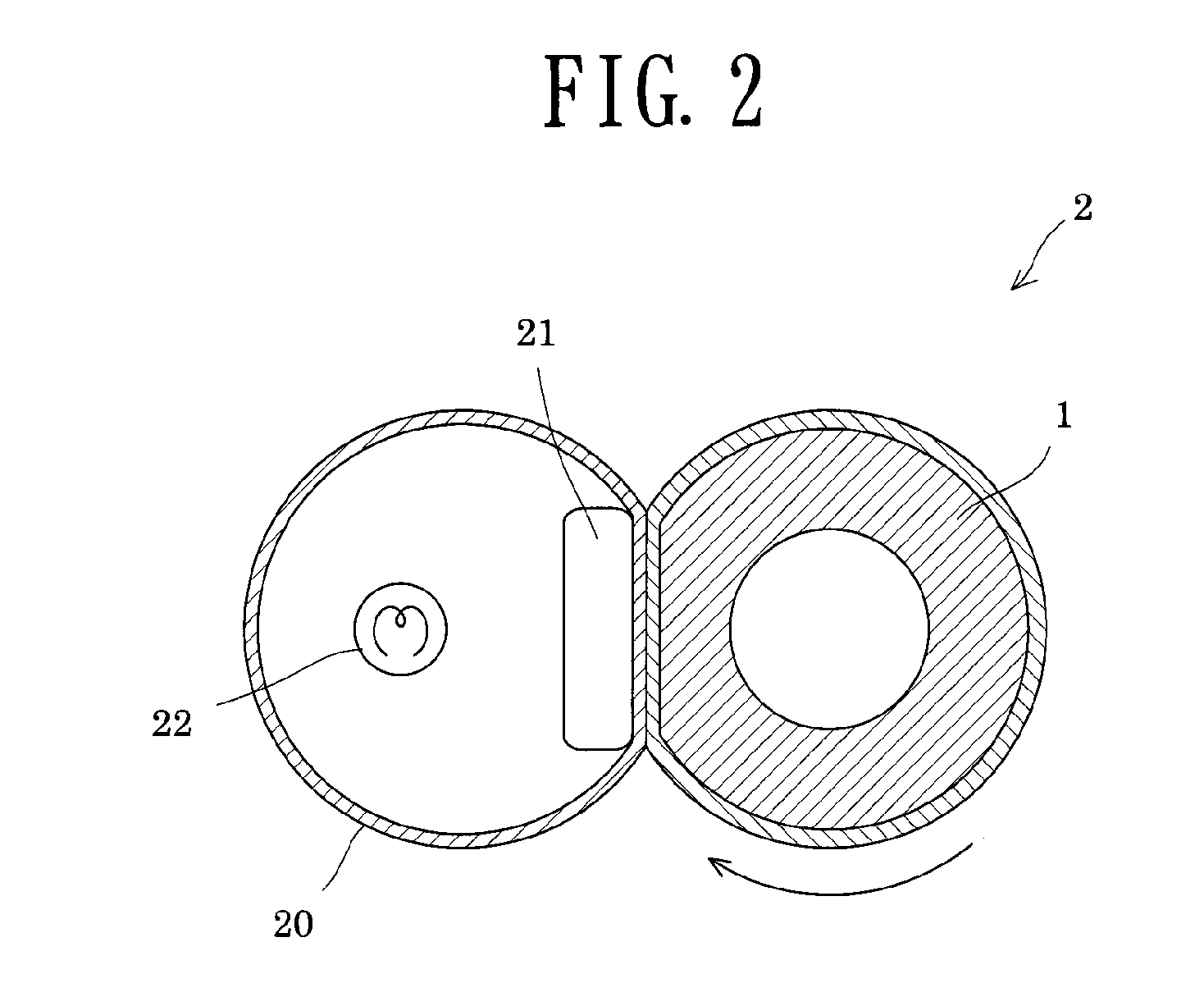
[0035]The fixing pressure roller of the present invention is employed for fixing an unfixed toner imager onto a recording medium by means of heat and pressure in a fixing unit of an image-forming apparatus. As described hereinbelow, the fixing pressure roller may be applied to, for example, a pressure roller or a fixing roller. In Embodiment 1, the fixing pressure roller is employed as a pressure roller.

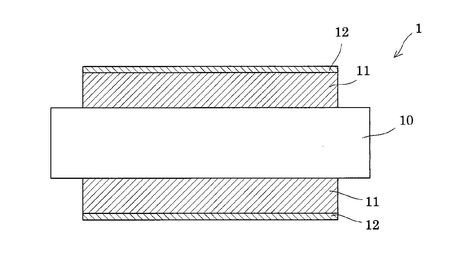
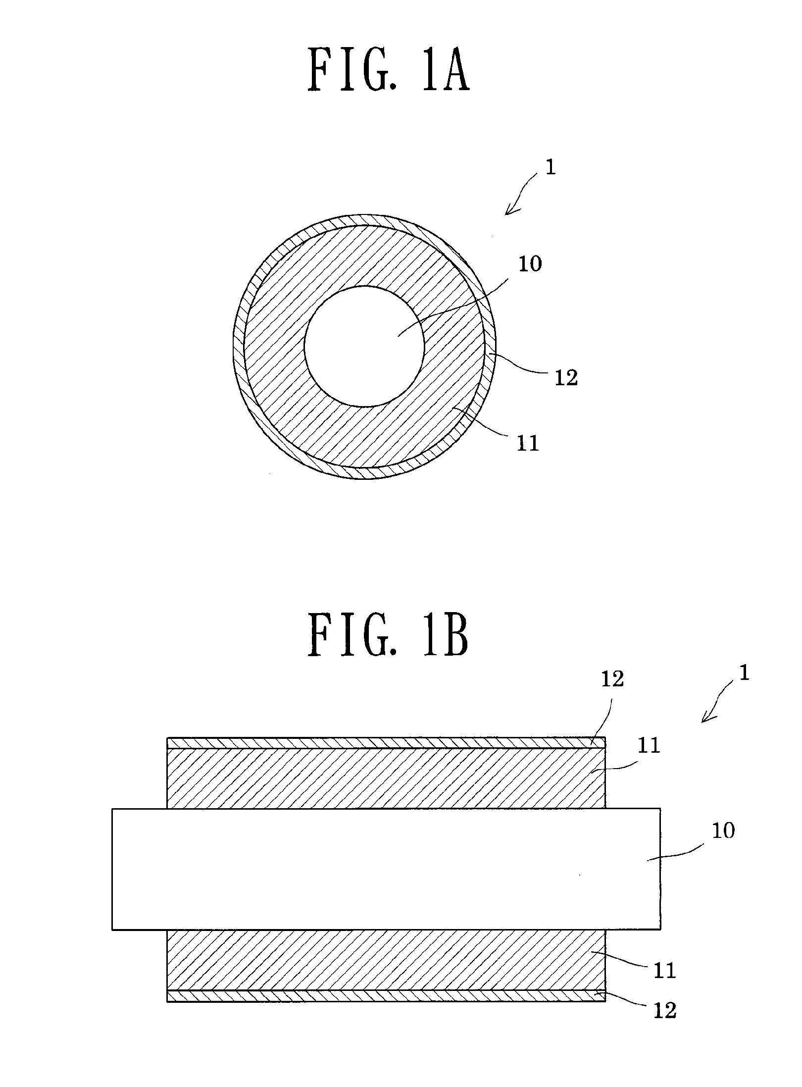
[0036]FIG. 1A is a transverse cross-sectional view of a pressure roller according to Embodiment 1, and FIG. 1B is a longitudinal cross-sectional view of the same pressure roller. The pressure roller 1 includes a core 10, an elastic layer 11 provided around the core 10, and a release layer 12 provided on the elastic layer 11.

[0037]In the present invention, the elastic layer 11 is formed of a silicone rubber product formed by mixing a raw silicone rubber with resin microballoons and water, to thereby prepare a dispersion, and then curing (heating) the raw silicone rubber. The silicone ...

embodiment 2

[0067]In Embodiment 2, the fixing pressure roller is employed as a fixing roller or a pressure roller. The members of the fixing device of Embodiment 2 which are the same as those of Embodiment 1 are denoted by the same reference numerals, and repeated descriptions thereof are omitted.

[0068]FIG. 3 is a cross-sectional view of the fixing device which includes a fixing roller and a pressure roller according to Embodiment 2. As shown in FIG. 3, the fixing device 2A includes the pressure roller 1; a fixing belt 20 provided so as to face the pressure roller 1; and a fixing roller 30 which is provided instead of a pressure member, and which applies pressure from the inside of the fixing belt 20 to the pressure roller 1. Non-illustrated heating means is provided outside of the fixing roller 30. The fixing pressure roller of the present invention 2 may serve as the fixing roller 30 or as the pressure roller 1, shown in FIG. 3.

embodiment 3

[0069]In Embodiment 3, the fixing pressure roller is employed as a fixing roller or a pressure roller. The members of the fixing device of Embodiment 3 which are the same as those of Embodiment 1 are denoted by the same reference numerals, and repeated descriptions thereof are omitted.

[0070]FIG. 4 is a cross-sectional view of the fixing device which includes a fixing roller and a pressure roller according to Embodiment 3. As shown in FIG. 4, the fixing device 2B includes the pressure roller 1; a fixing belt 20 provided so as to face the pressure roller 1; a fixing roller 30A which applies pressure from the inside of the fixing belt 20 to the pressure roller 1; and a heating roller 23 including therein heating means 22. The fixing roller 30A and the heating roller 23 are provided inside of the fixing belt 20, and the fixing belt 20 is rotated by means of the fixing roller 30A and the heating roller 23. The fixing pressure roller of the present invention may be employed serve as the f...


PUM


Abstract

To provide a fixing pressure roller having low roller hardness, low heat capacity, and low thermal expansion coefficient, and a fixing device including the fixing pressure roller. The fixing pressure roller of the invention for employment in a fixing unit of a fixing device has a core, and an elastic layer provided around the core, wherein the elastic layer is formed of a silicone rubber product formed by mixing a raw silicone rubber with resin microballoons and water, to thereby prepare a dispersion, and then curing the raw silicone rubber; and the silicone rubber product includes therein first voids provided from the resin microballoons and second voids which are smaller than the first voids and which are provided by evaporation of water.

Description

[0001]The entire disclosure of Japanese Patent Application No. 2013-230675 filed on Nov. 6, 2013 is expressly incorporated by reference herein.BACKGROUND OF THE INVENTION[0002]1. Field of the Invention[0003]The present invention relates to a pressure-applying fixing roller (hereinafter referred to as a “fixing pressure roller”) having an elastic layer, and to a fixing device having the fixing pressure roller, which fixing device is suitable for use in an image-forming apparatus.[0004]2. Background Art[0005]An image-forming apparatus such as a copying machine, a facsimile machine, or a laser beam printer has a fixing unit for fixing an unfixed toner image, and the fixing unit employs a fixing roller or the like. An example of such a fixing roller or the like has a metallic core, an elastic layer made of, for example, silicone rubber, and a release layer made of, for example, a fluororesin.[0006]Generally, the elastic layer of the fixing roller or the like is made of foamed silicone r...

Claims


Application Information

Patent Timeline
IPC IPC(8): G03G15/20
CPCG03G15/2089G03G15/206G03G2215/2025G03G2215/2035B05D3/007
Inventor NISHIDA, AKIRASUGIYAMA, SHINGOSUZUKI, MASAYA
Owner SYNZTEC
Learn More