Method of communication in a network

Inactive Publication Date: 2010-03-23
CANON KK
11 Cites 2 Cited by

AI-Extracted Technical Summary

Problems solved by technology

However, such systems are not relevant in the case where the network under consideration is a mixed network, that is to...

Benefits of technology

[0013]An advantage of the present invention is that it makes it possible to save energy.
[0014]Furthermore, the present invention makes it possible to avoid congesting the radio frequency space when there is no network user, since the temporary network is cut off in that case.
[0017]in case the authentication procedure is successful, the access point transmits a second beacon signal, as a result of which a temporary network is created.
[0025]if the authentication operations are successfully carried out, the access point transmits the second beacon signal.
[0026]This feature makes it possib...

Abstract

In a wireless communication network comprising at least one mobile terminal and an access point, the access point detects a beacon signal transmitted by a mobile terminal, and transmits a beacon signal in place of a given mobile terminal if it detects that the given mobile terminal transmits a beacon signal. The mobile terminal, on the other hand, stops transmitting the beacon signal and receives the beacon signal transmitted by the access point.

Application Domain

Unauthorised/fraudulent call preventionAssess restriction +5

Technology Topic

Beacon

Image

  • Method of communication in a network
  • Method of communication in a network
  • Method of communication in a network

Examples

  • Experimental program(1)

Example

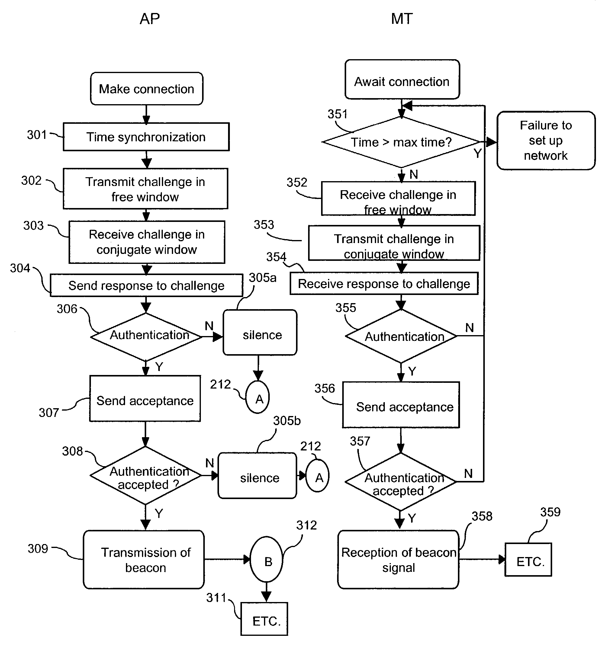
[0071]The object of the present invention is to create a beacon channel and thereby a wireless network, at the initiative of the mobile terminal, then to re-attribute this beacon channel to a point of access to the wired network, at the same time as the management of the access to the wireless network.
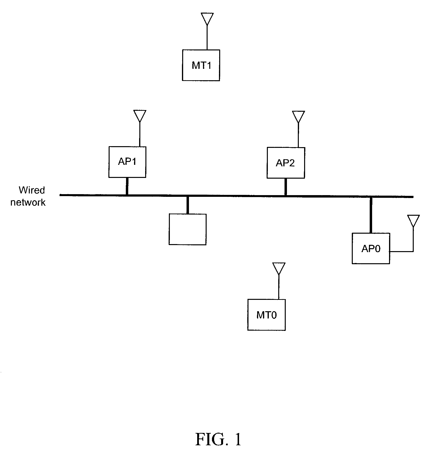
[0072]In a network such as that of FIG. 1 described above, all the terminals, whether they be mobile terminals or base stations, are capable of transmitting and receiving information over at least one beacon channel, in addition to their minimum capability of receiving or transmitting over a signaling channel, and vice-versa.
[0073]The mobile items of equipment must be capable of measuring a period of time.
[0074]The mobile terminals, as for the access points, possess an authentication system as well as an authentication key. This authentication key is held in a memory. This memory may be pre-loaded by the manufacturer or by a suitable system, as for example in a procedure for terminal—base station association by means of a cable, the manufacturer having pre-loaded the key in one of the two elements.
[0075]FIG. 2 shows the simplified architecture of an element of a network of the type of that in FIG. 1.
[0076]A transmitter-receiver 100 of the network comprises a radio module 200 and a data processing module 300 which contains a user data management module 20 as well as a network management module 10. This management module may create a beacon channel and receive the information from the signaling channel, or else it may create the signaling information and receive the beacon channel.
[0077]The radio module contains a frequency synthesizer 50 which is programmable by the network management module 10. This frequency synthesizer, with the aid of a mixer 60, makes it possible to modulate or demodulate the signals coming from [0078] a radio transmitter module 40, which transforms the binary signals output from the management modules 10 and 20 into a modulatable signal or [0079] a radio receiver module 30, which transforms the radio frequency signals into binary data understandable by the management modules 10 and 20.
[0080]An antenna 70 provides the interface with the outside.
[0081]The receiver module 30 contains an RSSI (Received Signal Strength Indicator) 35 which sends an indication to the management module 10.
[0082]FIG. 3 shows a possible architecture for the network management module 10.
[0083]This may be implemented with the use of conventional functions of a microcalculator. A clock 370 makes it possible to have a time base and to create time-outs.
[0084]A RAM memory 380 enables a large amount of data to be stored, a ROM memory 330 enables storage of the program to be executed, while a central processing unit 350 enables the sequential execution to be carried out of a certain number of instructions stored in ROM 330 or in RAM 380.
[0085]A random generator 360 which, as a variant, may be implemented purely in software form, is necessary. A radio module interface 340 enables the frequency synthesizer 50 to be driven. There may of course be an interface with other functions 310, whose processing it may be wished to integrate, as well as an interface with the wired or cabled network 320 if the member of the network under consideration is an access point.
[0086]As shown in FIG. 4, which illustrates the time-frequency domain used by the network, the structure of the network is such that a frame comprises several time windows, it being possible to attribute each window to a member of the network for the transmission of a signal. For each new frame, a given member of the network systematically uses that window until the end of the connection.
[0087]In each window, network management information as well as user data information are transmitted. The entirety of the management information is transmitted over several frames. This group is called a “super frame”.
[0088]The flow chart of FIG. 5 shows the succession of operations carried out by a mobile terminal, in accordance with the present invention. Let Nmax be the number of frequencies used by the network and let Tmax be a period greater than the transmission period of a frame.
[0089]When the user decides to use the wireless network from the mobile terminal which accompanies him, he communicates this intention via the man-machine interface. The mobile terminal then receives this call (step 100).
[0090]The terminal then initializes a register N with the value zero (step 101), then programs its frequency synthesizer to the frequency which corresponds to this index N=0 (step 102).
[0091]Then, for a period Tmax counted by a counter (test 108), the mobile terminal monitors the RSSI signal which gives it information on the energy received at the antenna (test 103). If this energy remains below a predetermined threshold, it is considered that no signal is received. The threshold is determined from constraints of the network, such as the admitted useful range and the power at the transmitter as well as the minimum required signal to noise ratio.
[0092]If a signal is received, the terminal awaits the following frame (test 104) to demodulate the management channel of the network (step 105) until a complete beacon signal is obtained normally, that is to say a complete super frame (test 106). When this is obtained, the connection-making procedure commences (step 107).
[0093]This branch has just described the case in which a network was preexisting. The connection is then made in a conventional manner.
[0094]If, during the whole period Tmax, the RSSI signal remained below the threshold (test 108 positive), then the index N is incremented by one unit (step 109).
[0095]If the number N is below the value of Nmax, the mobile terminal returns to step 102 and synthesizes the frequency corresponding to the index N+1.
[0096]If the number N is greater than the number Nmax (test 110 positive), it is considered that the terminal has explored the whole time-frequency domain and has not found any pre-existing network there. It must then create this network. To do this, it transmits (step 111) a beacon signal in a time window and at a frequency of its choice, and waits for a connection to be established (step 112).
[0097]The flow chart of FIG. 6 shows the succession of operations carried out by an access point belonging to the potential network.
[0098]On turning on, the access point initializes a register N with the value zero (step 201), then programs its frequency synthesizer to the frequency which corresponds to this index N=0 (step 202).
[0099]Next, for a period Tmax (test 208), the access point monitors the RSSI signal which gives it information on the energy received at the antenna (test 203). If this energy remains below a predetermined threshold, it is considered that no signal is received.
[0100]If a signal is received, the access point awaits the following frame (test 204) to demodulate the management channel of the network (step 205) until a complete beacon signal is obtained normally, that is to say a complete super frame (test 206). When this is obtained, a conventional connection-making procedure is commenced (step 207).
[0101]If, during the whole period Tmax, the RSSI signal remained below the threshold (test 208 positive), then the index N is incremented by one unit (step 209).
[0102]If the number N is below the value of Nmax, the access point returns to step 202 and synthesizes the frequency corresponding to the index N+1.
[0103]If the number N is greater than the number Nmax (test 210 positive), the access point returns to waiting for a beacon signal starting from step 201.
[0104]The flow chart of FIG. 7 shows the actual creation of the network, that is to say the first connection between access point and terminal. For ease of understanding, the steps corresponding to the access point (denoted AP in the drawing) are placed opposite those corresponding to the mobile terminal (denoted MT in the drawing).
[0105]After connecting the access point, a time synchronization step 301 is carried out. The beacon channel indicates the frequency-time windows domain, and so the access point knows, after complete reception of a super frame, in which window and at which frequency the terminal will be listening.
[0106]When this synchronization has been achieved, the access point transmits, in any one of the time windows, the fact that the terminal is listening (step 302).
[0107]In parallel, while awaiting a connection, the mobile terminal carries out a test 351 which makes it possible to indicate the failure of the commencement of the network if for example no access point that is on has been detected after a period “max time”.
[0108]The transmission made by the access point at step 302 contains a specific so-called “challenge” message. It is a random number destined to be encoded with the use of a private key algorithm. Let there be two entities A and B wishing to authenticate each other. The entities A and B both know the same key and will use the same encryption algorithm. A sends a random number to B. A and B carry out a predefined calculation with this random number as operand. Next, B sends A the result of its calculation. A then compares this result with its own result and if the two are identical, A has authenticated B.
[0109]This challenge is received at step 352 by the mobile terminal, which transmits the response to the challenge within the conjugate time window (or slot), followed by a new challenge.
[0110]It should be recalled that each communication between A and B uses a slot for the transmission from A to B and a slot for the transmission from B to A, and that these two slots are said to be conjugates of each other.
[0111]This message is received by the access point at step 303. At step 353, the mobile terminal sends the access point a message with the response to the challenge sent out by the access point as well as a challenge which it has created. At step 304, the access point sends a message back to the mobile terminal with the response to the challenge sent out by the mobile terminal.
[0112]The mobile terminal receives this response at step 354. Here, of course, the procedure has been simplified and account has not been taken of possible re-transmissions in case of error, the correct transmission of the data being ensured by the person skilled in the art knowing these methods.
[0113]The access point, having sent out a challenge and received a response, can authenticate the mobile terminal at step 306. If the authentication fails, the access point ceases all transmission at step 305a and remains silent, then resumes the process from the connector A 212, that is to say at step 201 of FIG. 6.
[0114]If the authentication is successfully carried out, the access point sends a message to the mobile terminal to inform it of this (step 307), then awaits the confirmation of its own authentication by the mobile terminal (step 308). If this confirmation is not received, as previously, the access point becomes silent (step 305b) then resumes the process in A (212), that is to say at step 201 of FIG. 6.
[0115]Otherwise, at a step 309, the confirmation of the authentication having been received, the access point undertakes the transmission of the beacon signal.
[0116]Thus, a temporary network is created and its existence continues in a conventional manner, as shown in the drawing by “ETC.” (step 311).
[0117]For the mobile terminal, on reception from the access point of the response to the challenge coming from the mobile terminal, the verification of whether or not the access point belongs to the network is established at an authentication step 355.
[0118]If the authentication fails, the process resumes at 351. When the authentication is achieved, the mobile terminal sends the access point a message of acceptance (step 356) and awaits confirmation of its own authentication by the access point (test 357). If this confirmation is not obtained, the process resumes at test 351.
[0119]If the confirmation is obtained, then the mobile terminal stops transmitting the beacon signal, transmits that for signaling and receives the new beacon signal (step 358). The method then continues in conventional manner, as is summarized on the drawing by “ETC.” (step 359).
[0120]The flow chart of FIG. 8 shows the end of the temporary network. When the mobile terminal terminates the connection (step 400), the access point continues to transmit a beacon signal for a predetermined time (step 401), in order permit the possibility of a terminal establishing a new connection.
[0121]If a new connection is detected (test 402), the temporary network continues its existence in conventional manner, that is to say that connector B 312 of FIG. 7 is proceeded to.
[0122]If the time limit for waiting for a new connection is exceeded (test 401 positive), the beacon signal is no longer transmitted (step 405) and the access point proceeds to the connector A 212, that is to say at step 201 of FIG. 6. As for the mobile terminal, it is deactivated or reactivated by the user.
[0123]The algorithms described above may be implemented either in the form of hardware or software.

PUM

no PUM

Description & Claims & Application Information

We can also present the details of the Description, Claims and Application information to help users get a comprehensive understanding of the technical details of the patent, such as background art, summary of invention, brief description of drawings, description of embodiments, and other original content. On the other hand, users can also determine the specific scope of protection of the technology through the list of claims; as well as understand the changes in the life cycle of the technology with the presentation of the patent timeline. Login to view more.

Similar technology patents

Energy saver cycle

InactiveUS20160208428A1energy savelong operation
Owner:MABE SA DE CV

System and a method of adaptively controlling an LED backlight

InactiveUS20130162701A1enhance image contrastenergy save
Owner:HIMAX MEDIA SOLUTIONS

Relating to propylene oxide purification

ActiveUS20150158835A1energy save
Owner:SHELL USA INC

Method for Controlling or Regulating the Air Pressure in a Compressed Air Supply Device

InactiveUS20090133394A1decrease efficiencyenergy save
Owner:KNORR-BREMSE SYST FUER NUTZFAHRZEUGE GMBH

Classification and recommendation of technical efficacy words

  • energy save

Remote Control Water Valving System for Shower or Sink

InactiveUS20090261282A1encourage useenergy save
Owner:CONNORS PAUL E

Programmable energy saving register vent

InactiveUS20070298706A1energy savereduce amount of energy
Owner:SPRINGFIELD ACQUISITION CO LLC

Multiple laundry treating machine

InactiveUS20100005681A1energy saveconvenience in use
Owner:LG ELECTRONICS INC

Electric Fireplace Heater Having LED Flame Simulator

InactiveUS20090080871A1long life spanenergy save
Owner:CHIU HSIEN JUNG
Why Eureka
Try Eureka