
Product support and dispensing system for a vending machine

a technology of product support and dispensing system, which is applied in the field of vending machines, can solve the problems of increasing the overall assembly time, undesirable flexibility of vending machine, and high manufacturing cost, and achieves the effect of improving product retention

Inactive Publication Date: 2010-03-23
CRANE MERCHANDISING SYSTEMS
View PDF35 Cites 6 Cited by
  • Summary
  • Abstract
  • Description
  • Claims
  • Application Information

AI Technical Summary

Benefits of technology

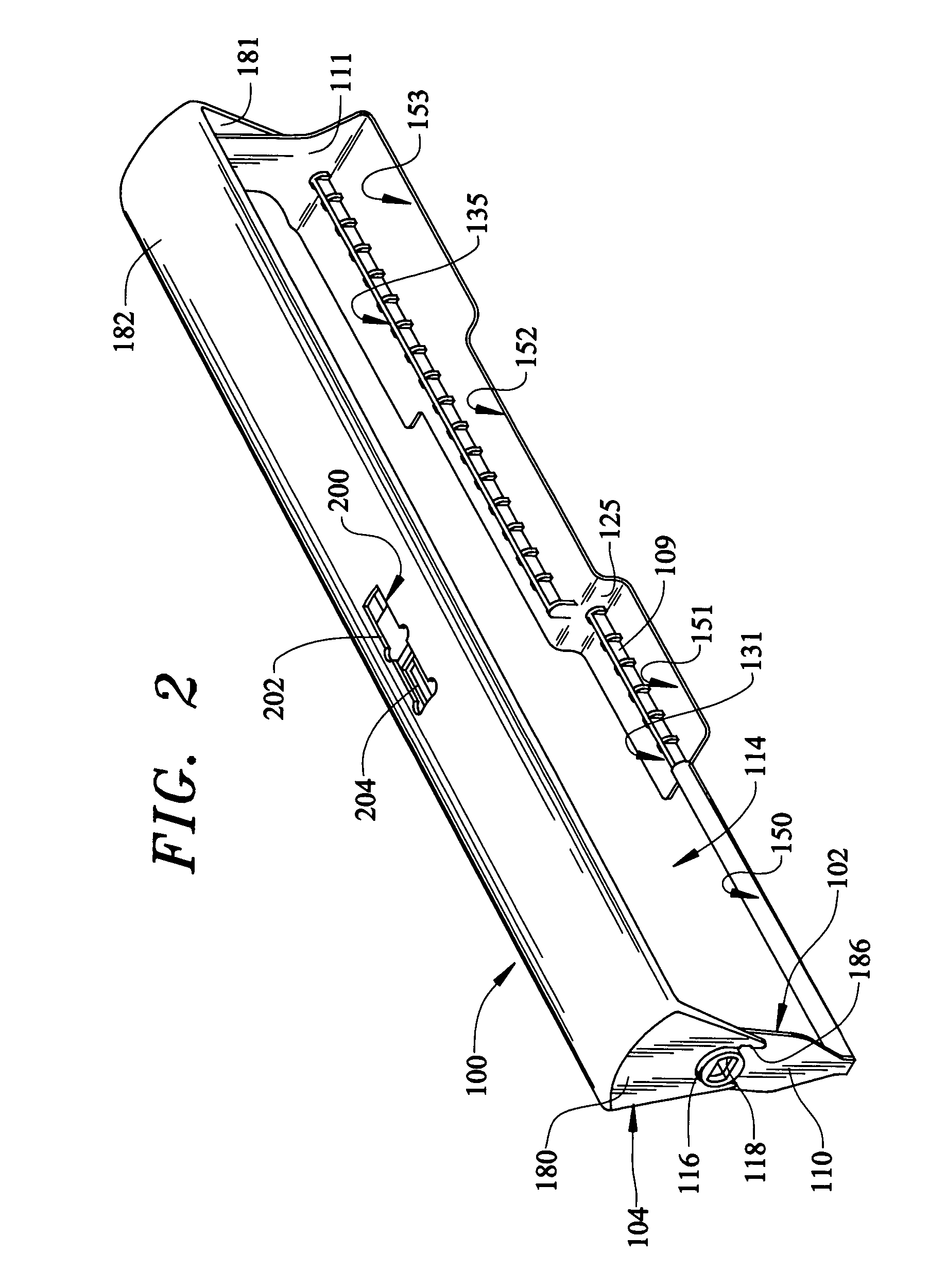
[0009]The present invention is directed to use of a stepped oscillator arrangement in an overall dispensing system in a vending machine. One aspect of the invention is to provide a dispensing oscillator for a vending machine which exhibits enhanced product retention. In accordance with a preferred embodiment of the invention, at least one step is formed in the oscillator in a manner which creates retention in three dimensions. This additional retention dimension, in combination with notches provided on the oscillator, enables 4-deep can vending. In addition, the retention feature further enables a singly designed vending machine to be used in dispensing a multitude of different products with requiring complex changeovers or additional parts.
[0010]In further accordance with the invention, the stepped oscillator is designed to reduce the effective drop height for the dispensed products. More specifically, in a single step configuration, the step is configured to follow a slope of a product chute associated with the vending machine. In this manner, the dispensed product generally rides along the chute when dispensed. This arrangement functions to reduce agitation of the contents, thereby minimizing the possibility of the product spewing out of the container upon opening.
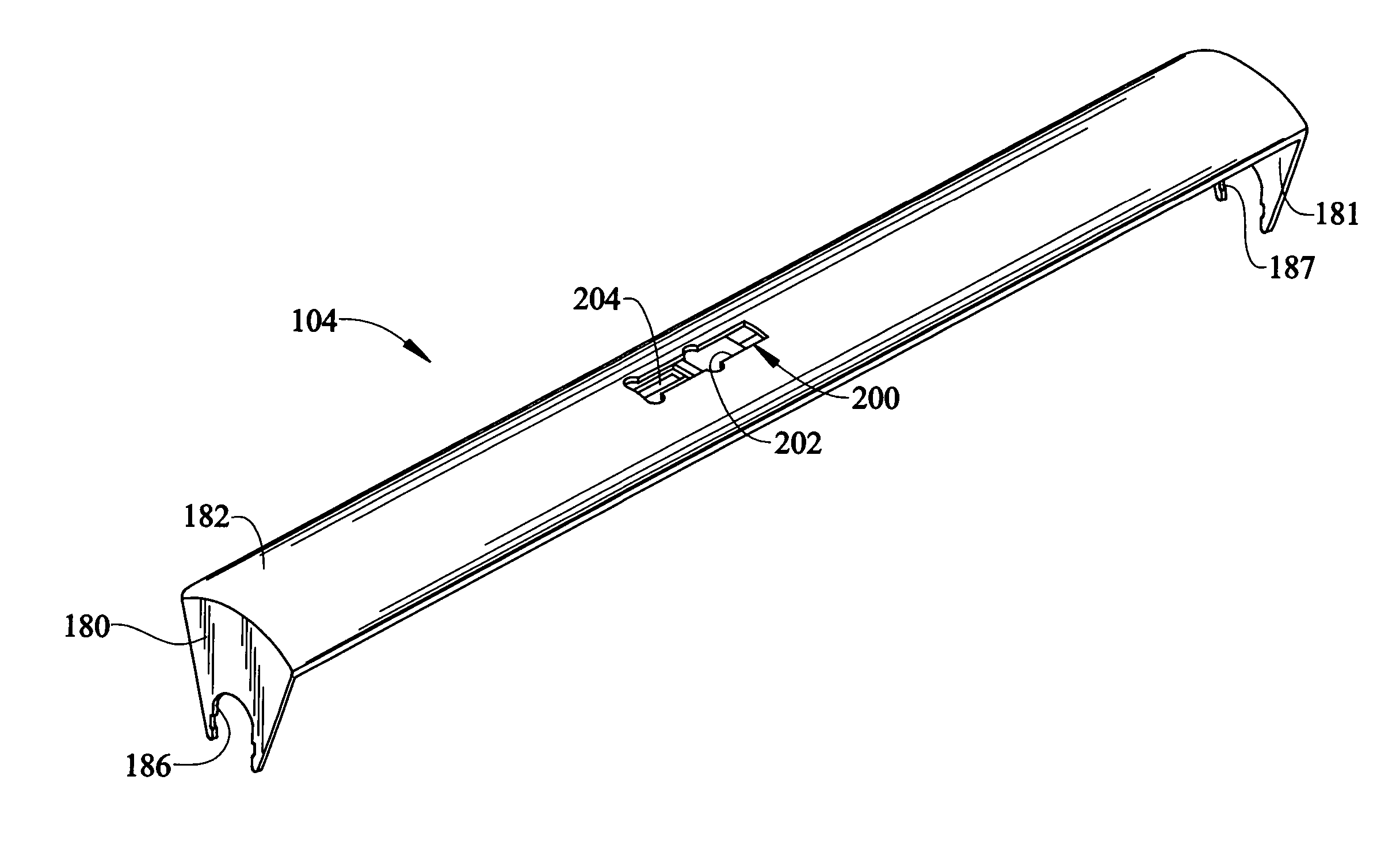
[0012]The bail cap arrangement of the invention provides various advantages in connection with a vending machine oscillator. First, the bail cap functions to stage and isolate products in a ready-to-vend state from the stored product. This separation function eliminates excessive force of aggregate stored product directly on the oscillator. In this manner, the actual vending area is more controllable and reliability is increased.
[0013]In addition, the inclusion of the bail cap eliminates the lifting of stored product by the oscillator. That is, the bail cap maintains the next-to-load product supply in an optimum position for loading such that, when the products carried by the oscillator are all dispensed, the next-to-load products are not actually lifted prior to being seated on the oscillator. This advantageous feature substantially eliminates the potential for product crushing, avoids product lifting requirements, and prevents undo product pinching. All of these features contribute to prevent unnecessary motor or product jamming, as well as column wall bowing in the product stack.
[0014]By controlling the relative angular position between the oscillator and the bail cap, the overall product flexibility of the dispensing system is enhanced. More specifically, shifting of the adjustment slide alters the oscillating travel arc. This adjustability particularly increases the ability of the oscillator to accommodate varying diameter packages. In accordance with the most preferred embodiment of the invention, a manually adjusted slide mechanism is utilized for this purpose. The slide mechanism acts to interconnect the oscillator and the bail arm, while defining stop structure adapted to abut the oscillator to limit the permissible travel arc. In the most preferred form of the invention, the slide mechanism can be arranged in one of two alternative positions, although it is envisioned that further positions could be made available. As an alternative arrangement, the bail cap itself could be reversed end-to-end to establish the different stop positions.

Problems solved by technology

Obviously, requiring these additional components to provide vending flexibility is undesirable, costly to manufacture, and increases overall assembly time.
To this end, problems of product crushing, lifting and / or pinching can develop which, in turn, can cause motor or product jams, stack or column wall bowing, and the like problems.

Method used


Image

  • Product support and dispensing system for a vending machine
  • Product support and dispensing system for a vending machine
  • Product support and dispensing system for a vending machine

Examples


Embodiment Construction

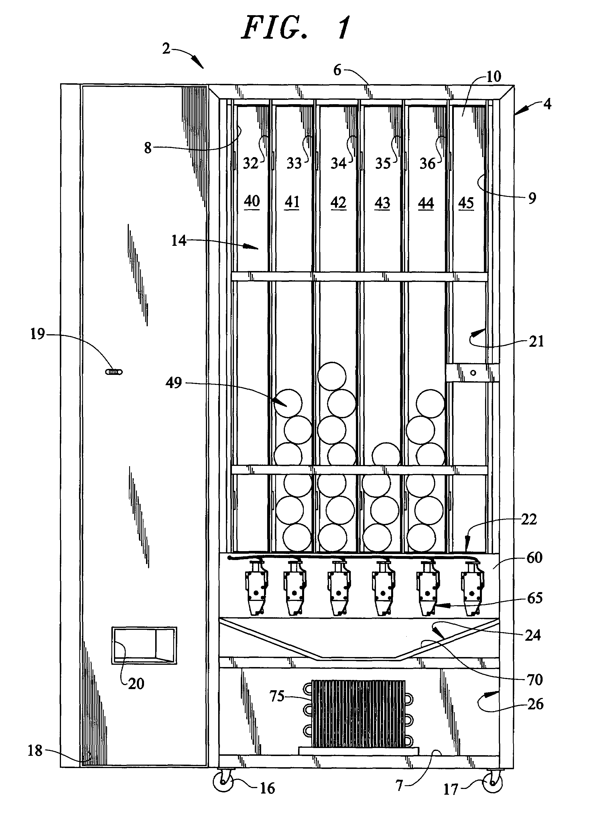
[0031]With initial reference to FIG. 1, a vending machine 2 includes a cabinet frame 4 having top, bottom, side and rear walls 6-10 that collectively define a central cavity 14. In a manner known in the art, a first pair of wheels or casters 16 and 17 are secured to a front edge portion of bottom wall 7 to facilitate the positioning of vending machine 2. Of course it should be realized that a second pair of wheels (not shown) are also arranged on a rear portion of bottom wall 7. A door 18 is pivotally mounted to cabinet frame 4 to selectively enable access to central cavity 14 in order to load various product containers or other commodities into vending machine 2. Door 18 is provided with a locking mechanism, shown in the form of a threaded rod 19, to retain door 18 in a closed position so as to prevent pilfering of the commodities from central cavity 14. Door 18 is also provided with an opening 20 to enable a consumer to remove a vended product container or other commodity from ven...


PUM


Abstract

A vending machine incorporates a product support and dispensing system including an oscillator and an adjustable bail cap. The oscillator is pivotally mounted at a lower portion of one of a plurality of stack areas provided within the vending machine. The oscillator includes a product retention zone having first and second staging regions, each of which has upper and lower holding elements for retaining a product containers in pre-vend positions. The adjustable bail cap is detachably secured to the oscillator and includes an arcuate intermediate portion adapted to selectively support the product containers. The adjustable bail cap can be selectively repositioned to allow the product support and delivery system to accommodate a wide range of container sizes.

Description

CROSS-REFERENCE TO RELATED APPLICATIONS[0001]The present application claims benefit of both U.S. Provisional Patent Application Serial No. 60 / 415,744 entitled “VENDING MACHINE OSCILLATOR DISPENSING SYSTEM” filed on Oct. 4, 2002 and U.S. Provisional Patent Application Ser. No. 60 / 415,747 entitled “VENDING MACHINE WITH OSCILLATOR DISPENSING SYSTEM INCORPORATING BAIL CAP” filed on Oct. 4, 2002.BACKGROUND OF THE INVENTION[0002]1. Field of the Invention[0003]The present invention pertains to the art of vending machines and, more particularly, to an oscillator-type dispensing system for a vending machine.[0004]2. Discussion of the Prior Art[0005]Vending machines are commonly utilized in dispensing a wide range of products, including canned and bottled beverages, edible food items, and other consumer products. In the case of dispensing beverage products, it is desirable to configure a vending machine such that it is capable of dispensing various different sized and configured beverage cont...

Claims


Application Information

Patent Timeline
IPC IPC(8): G07F17/00B65H3/26G07F11/24
CPCG07F11/24B65G2201/0252
Inventor KELLY, PAUL HAYWARDPOWELL, JOSHUA ROBERTRICHARDSON, EDMUND SCOTTSAMSON, JOHN T.STEVENS, MICHAEL E.
Owner CRANE MERCHANDISING SYSTEMS
Learn More