Packaging structure for depression switches

a technology of depression switch and packaging structure, which is applied in the direction of contact surface shape/structure, snap-action arrangement, contact, etc., can solve the problems of easy air trapped in the metal dome switch, difficult switch depression, and suffer from click feeling

Inactive Publication Date: 2010-03-30
YUANHAN MATERIALS INC
View PDF15 Cites 9 Cited by
  • Summary
  • Abstract
  • Description
  • Claims
  • Application Information

AI Technical Summary

Benefits of technology

[0005]The primary object of the present invention is to provide a packaging structure for depression switches to prevent loss of air in a metal dome switch under depression. To achieve the foregoing object, the packaging structure of the invention includes an electronic substrate with at least one switch electrode located thereon, a push-on switch located on the electronic substrate to connect the switch electrode to generate a command signal, and a sealing member. The push-on switch and the electronic substrate form a first air chamber between them. The sealing member has a fastening portion to seal the push-on switch on the electronic substrate and a second air chamber between the electronic substrate and thereof communicating with the first air chamber.
[0010]By means of the invention, when the push-on switch is depressed to connect the switch electrode, the first air chamber is squeezed and the air inside flows to the second air chamber. When the depressing force is released, the air in the second air chamber flows back to the first air chamber. Hence the air held inside the switch does not flow out to the IC card and does not damage the packaging structure thereof. Moreover, the air pressure resulting from the air flowing back from the second air chamber to the first air chamber can quickly return the push-on switch to its original condition and improve the response speed of the push-on switch.

Problems solved by technology

During manufacturing processes to install the metal dome switch on a printed circuit board (PCB in short hereinafter), air often is trapped in the metal dome switch.
The trapped air makes depression of the switch difficult and click feeling suffered.
However, the conventional techniques mentioned above cannot be used on IC cards embedded with a metal dome switch. FIGS. 1A and 1B illustrate a conventional IC card 1.
As a result, a packaging and sealing defect occurs.

Method used


Image

  • Packaging structure for depression switches
  • Packaging structure for depression switches
  • Packaging structure for depression switches

Examples


Embodiment Construction

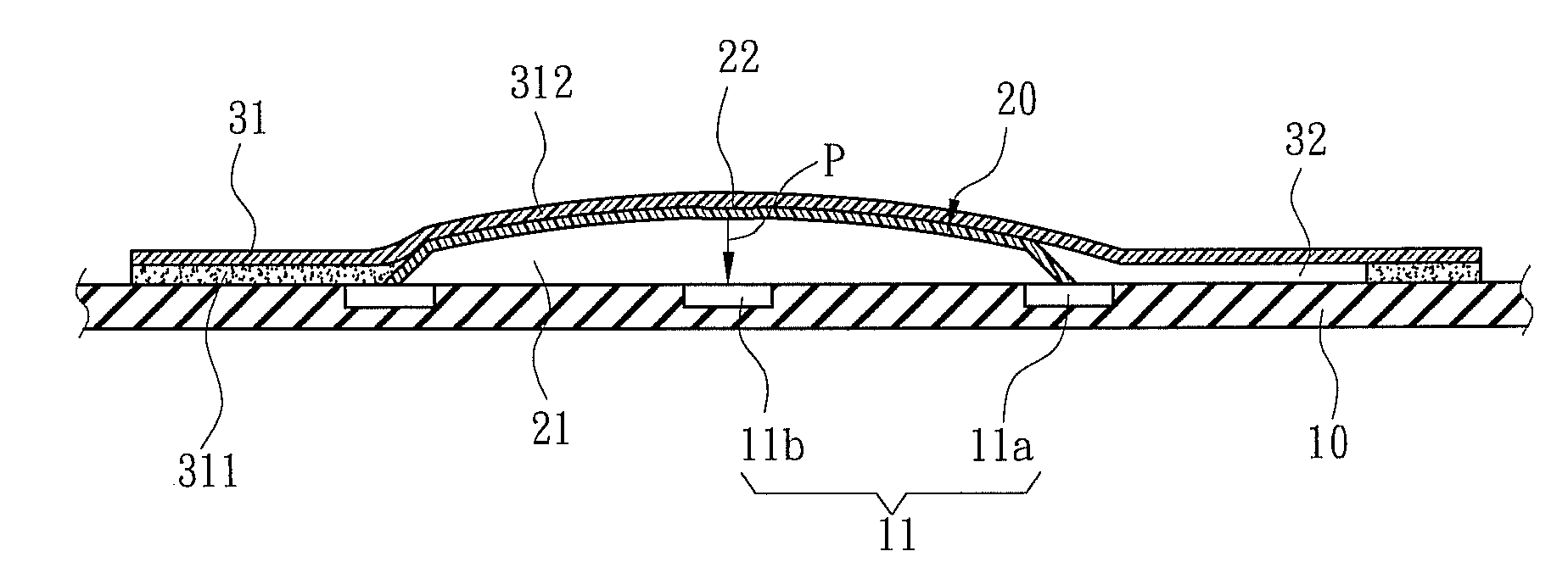
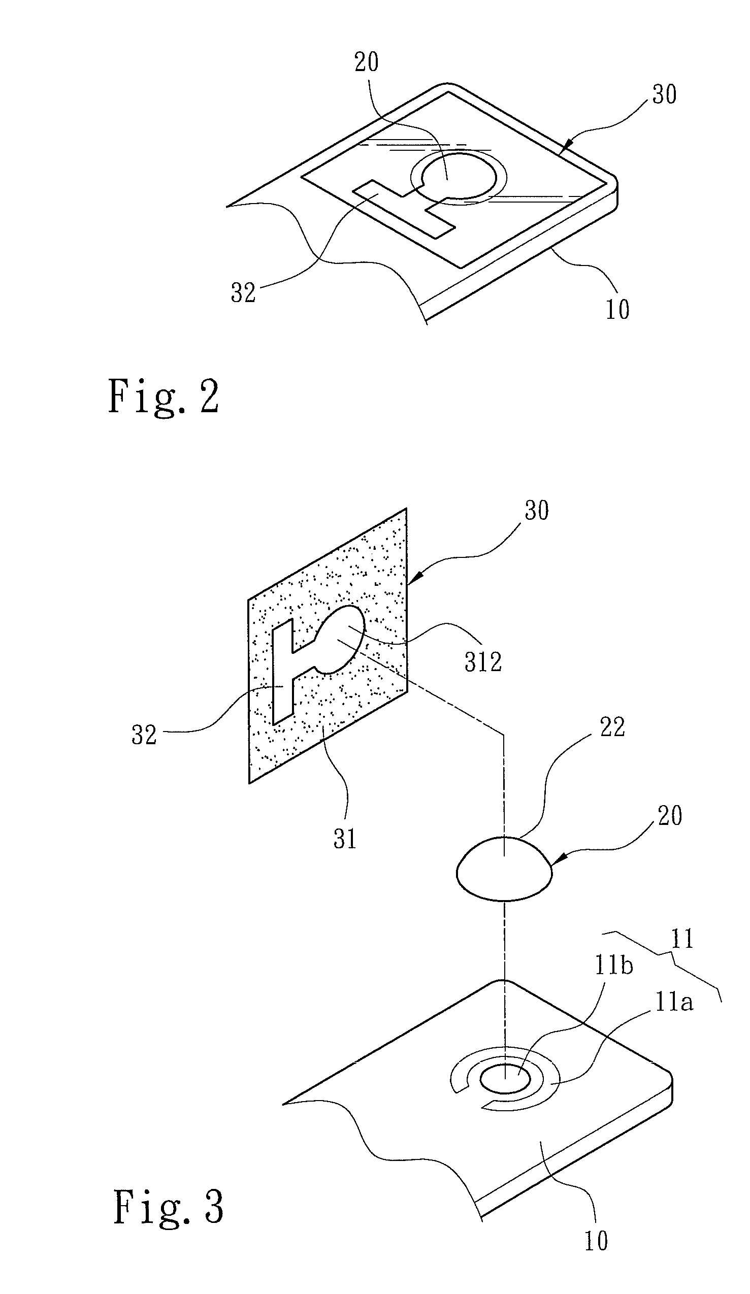
[0017]Please refer to FIGS. 2, 3 and 4A for an embodiment of the invention. A packaging structure for depression switches of the invention includes an electronic substrate 10 containing at least one switch electrode 11, a push-on switch 20 located on the electronic substrate 10 to connect the switch electrode 11 to generate a command signal, and a sealing member 30 to encase the push-on switch 20. The push-on switch 20 is located above the switch electrode 11 and has a first air chamber 21 formed between thereof and the electronic substrate 10 and a depressing portion 22 above the first air chamber 21. The depressing portion 22 is depressible for a depression distance P in the first air chamber 21 to trigger the switch electrode 11. The sealing member 30 has a fastening portion 31 to seal the push-on switch 20 on the electronic substrate 10 and a second air chamber 32 between the electronic substrate 10 and thereof communicating with the first air chamber 21.

[0018]In the embodiment,...


PUM


Abstract

A packaging structure for depression switches includes an electronic substrate containing at least one switch electrode, a push-on switch located on the electronic substrate to connect the switch electrode to generate a command signal and a sealing member. The push-on switch and the electronic substrate form a first air chamber between them. The sealing member has a fastening portion to seal the push-on switch on the electronic substrate and a second air chamber formed with the electronic substrate to communicate with the first air chamber. By depressing the push-on switch to connect the switch electrode, air held in the first air chamber is squeezed and flows to the second air chamber without escaping.

Description

FIELD OF THE INVENTION[0001]The present invention relates to a packaging structure and particularly to a packaging structure for depression switches.BACKGROUND OF THE INVENTION[0002]Metal dome switch is a thin switch widely used on mobile communication devices, input devices of computer systems or IC cards. It usually contains a thin and arched metal blade and can provide metallic characteristics such as electric conductivity and elasticity.[0003]During manufacturing processes to install the metal dome switch on a printed circuit board (PCB in short hereinafter), air often is trapped in the metal dome switch. The trapped air makes depression of the switch difficult and click feeling suffered. Many techniques have been proposed to expel the air trapped in the metal dome switch. References can be found in U.S. Pat. Nos. 5,901,834, 6,441,330, 6,531,671, 6,917,007, 6,982,394 and 7,145,092. They mostly have an opening or a conduit formed on the bounding surface between the metal dome swi...

Claims


Application Information

Patent Timeline
Patent Type & Authority Patents(United States)
IPC IPC(8): H01H13/715
CPCH01H13/705H01H2205/016H01H2205/018H01H2213/014H01H2231/05
Inventor CHIEN, MING-CHIHCHEN, JUNG-HSIU
Owner YUANHAN MATERIALS INC
Why Eureka
Try Eureka