Node merging process for network topology representation

a network topology and node technology, applied in the field of communication networks, can solve the problems of difficult to recognize important features of the network topology, limit the number of nodes and edges that can be effectively presented, and large network topologies that are difficult to visualize and interpret, so as to achieve accurate simplified networks

Active Publication Date: 2010-03-30
AVAYA INC
View PDF13 Cites 12 Cited by
  • Summary
  • Abstract
  • Description
  • Claims
  • Application Information

AI Technical Summary

Benefits of technology

[0013]Advantageously, the present invention in the illustrative embodiments provides an improved approach to generation of network topology representations. This approach is simple and efficient, and can accurately simplify a given network topology to present, for example, only those portions of the network likely to be associated with WAN components.

Problems solved by technology

Large network topologies can be very difficult to visualize and interpret.
For example, the physical constraints of the display may limit the number of nodes and edges that can be effectively presented.
In addition, it may be difficult to recognize important features of the network topology when the topology also includes many unimportant nodes and edges.
This coloring process is typically based on lengthy calculations, and so can be difficult to implement with large network topologies.
The conventional approaches noted above fail to provide an adequate mechanism for automatically simplifying the visualization so as to present only particular portions of interest.
Unfortunately, the conventional techniques are unable to simplify a network topology visualization such that it automatically presents only those nodes and edges likely to represent WAN components of the network.

Method used


Image

  • Node merging process for network topology representation
  • Node merging process for network topology representation
  • Node merging process for network topology representation

Examples


Embodiment Construction

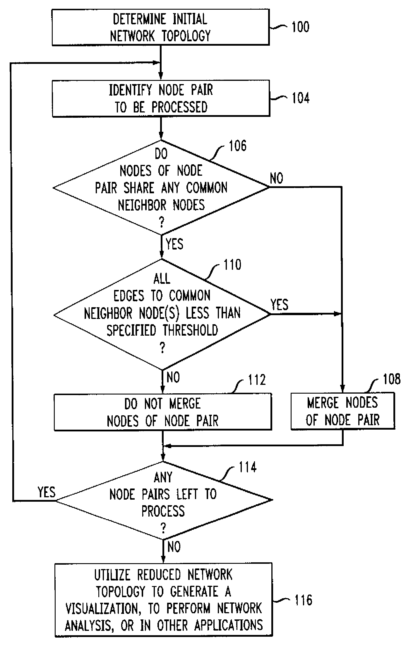
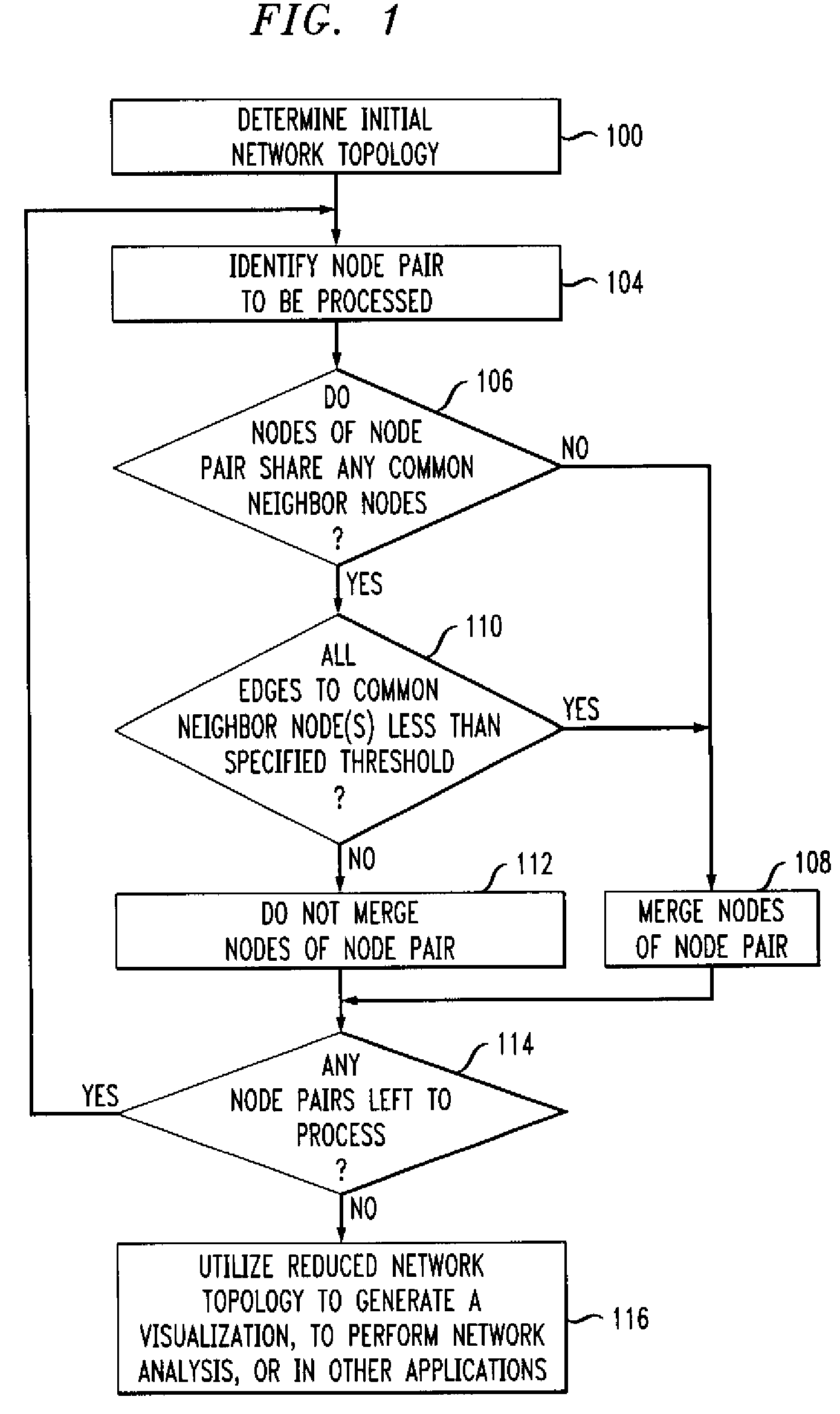
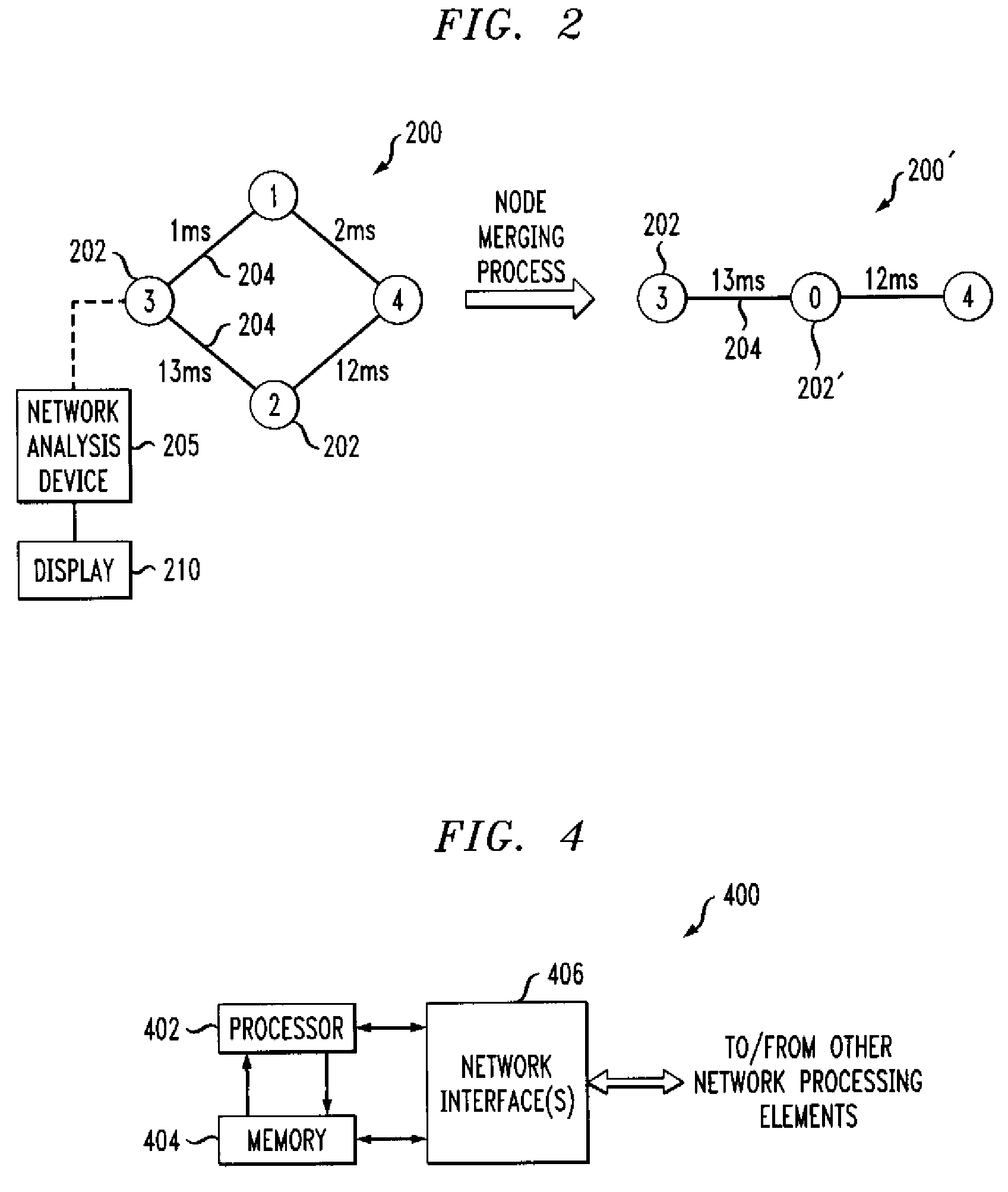
[0018]The invention will be illustrated below in conjunction with various arrangements associated with an exemplary node merging process for generating simplified representations of network topology. It should be understood, however, that the invention is not limited to use with any of these particular illustrative arrangements. For example, although the disclosed techniques are particularly well-suited for use in generating simplified visualizations of network topology, those skilled in the art will recognize that these techniques may be adapted for use in any type of application that can benefit from a reduced network topology.

[0019]The term “network topology” as used herein is intended to be construed broadly, so as to encompass any type of representation comprising nodes and edges. A given network topology may thus represent the topology associated with a particular network layer, such as Layer 3, but may alternatively include other layers or combinations of layers, as well as v...


PUM


Abstract

Node merging methods and apparatus are disclosed for generating simplified representations of network topology. A first topology representative of a given network is determined, and at least one pair of nodes of the first topology is merged into a single node based on measures associated with respective edges connecting the nodes of the node pair to at least one neighbor node common to that pair. The merging step is repeated for one or more additional pairs of nodes to produce a reduced network topology meeting one or more desired criteria, and a visualization or other representation of the reduced network topology is generated.

Description

FIELD OF THE INVENTION[0001]The invention relates generally to communication networks, and more particularly to techniques for processing information representative of network topology.BACKGROUND OF THE INVENTION[0002]As is well known, the topology of a given communication network may be generally represented as comprising nodes interconnected by edges. The nodes may represent network elements such as, for example, routers, switches and gateways, while the edges represent connections between such elements. Information specifying a network topology may be stored in the form of a designated data structure, such as a list of nodes and a corresponding adjacency matrix specifying connections between the nodes.[0003]Network topology information is useful in a wide variety of applications, including applications that involve network analysis associated with implementation, maintenance, management, monitoring or troubleshooting of communication networks. As a more particular example, it is ...

Claims


Application Information

Patent Timeline
Patent Type & Authority Patents(United States)
IPC IPC(8): H04L12/28
CPCH04L41/12H04L43/0852
Inventor DENBY, LORRAINEMELOCHE, JEANRAO, BALAJI SATHYANARAYANATUCK, JR., JOHN R.
Owner AVAYA INC
Why Eureka
Try Eureka