Channel-mounted 4-bar linkage assembly

a technology of linkage and channel, applied in the direction of door/window fittings, wing operation mechanisms, constructions, etc., can solve the problems of inability to work, inability to accommodate the stack height of the linkage, and inability to adjust the height of the channel

Active Publication Date: 2010-04-06
CALDWELL MFG NORTH AMERICA
View PDF29 Cites 13 Cited by
  • Summary
  • Abstract
  • Description
  • Claims
  • Application Information

AI Technical Summary

Benefits of technology

[0005]The invention features a linkage assembly, which among its various embodiments incorporates adaptations for exploiting advantages of the “Euro-Groove” mounting system while overcoming attendant clearance limitations. The embodiments include 4-bar linkage assemblies in which modified vent bars engage conventional mounting channels. A base portion of one such vent bar slides within the conventional channel, an offset portion of the same bar abuts one end of the channel sidewalls, and a fixed connection between the base and offset portions projects through overhanging side rails of the channel. A spacing feature provides rotational clearance between the intermediate linkage and the sidewalls, supporting rotation of the intermediate linkage with respect to the vent bar mounted within the channel. Thus, the modified linkages can be both anchored to and located along conventional mounting channels, while preserving the intended functions and desired thicknesses of their linkage bars.
[0006]One version of the invention as a linkage assembly for pivotally mounting a sash to a frame includes a vent bar that is slidable within a channel of the sash into a fixed mounting position. The vent bar has a length that can be oriented along the sash channel and a width that can be overhung by sidewalls the sash channel. One end of an intermediate linkage pivotally connects to the vent bar. A track is attachable to a channel of the frame, and a shoe slides along the track. Another end of the intermediate linkage pivotally connects to both the track and the shoe. A spacing feature provides rotational clearance between the intermediate linkage and the sidewalls of the sash channel in support of a rotation of the intermediate linkage with respect to the vent bar mounted within the sash channel.
[0011]The offset portion of the vent bar also preferably includes a tip formed at one end of the vent bar for engaging a camming surface at one end of the track. The offset portion can be spaced from the base portion of the vent bar in a position that provides rotational clearance between the intermediate linkage and the sidewalls of the sash channel. The base portion of the vent bar also supports a pivotable connection to the intermediate linkage. A spacing feature between the base portion of the vent bar and the intermediate linkage can be sized for projecting between the overhanging portions of the sidewalls of the sash channel. The spacing feature provides rotational clearance between the intermediate linkage and the sidewalls of the sash channel in support of a rotation of the intermediate linkage with respect to the vent bar mounted within the sash channel.
[0013]Yet another version of the invention as a window assembly includes channels in both a frame and a sash for mounting hardware. The sash channel has a channel bottom and sidewalls that include overhanging portions that overhang the channel bottom. The frame channel and the sash channel define a limited clearance between positions of overlap. A track is anchored to the frame channel, and a shoe slides along the track. A vent bar located along the sash channel has a base portion overhung by the overhanging portions of sidewalls. An intermediate linkage connects the vent bar to both the track and the shoe. A spacing feature provides rotational clearance between the intermediate linkage and the sidewalls of the sash channel in support of a rotation of the intermediate linkage with respect to the vent bar.

Problems solved by technology

Although many benefits accrue from such standardized mounting systems, the channels can impose clearance limitations, particularly for linkages that support pivotal and translational motions of casement windows.
For example, such channels can provide strong anchors for securing conventional 4-bar linkages to mating sashes and frames of casement windows, but the opposing channels between the sashes and frames can limit the space available for accommodating a stack height of the linkages.
However, this solution is not workable for some heavy-duty applications, where the demands on the linkages are severe.

Method used


Image

  • Channel-mounted 4-bar linkage assembly
  • Channel-mounted 4-bar linkage assembly
  • Channel-mounted 4-bar linkage assembly

Examples


Embodiment Construction

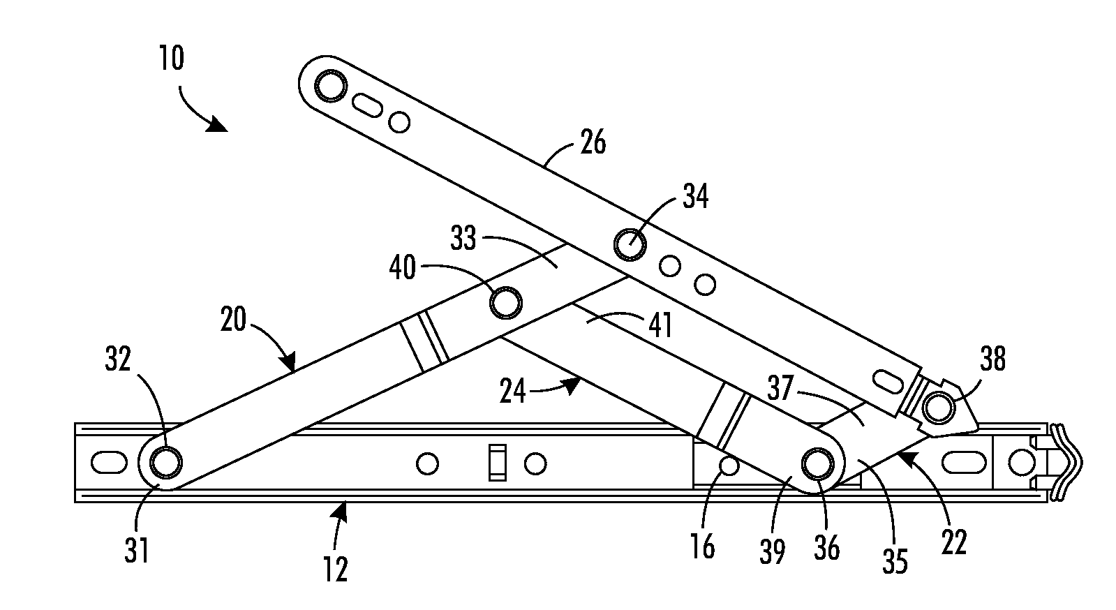
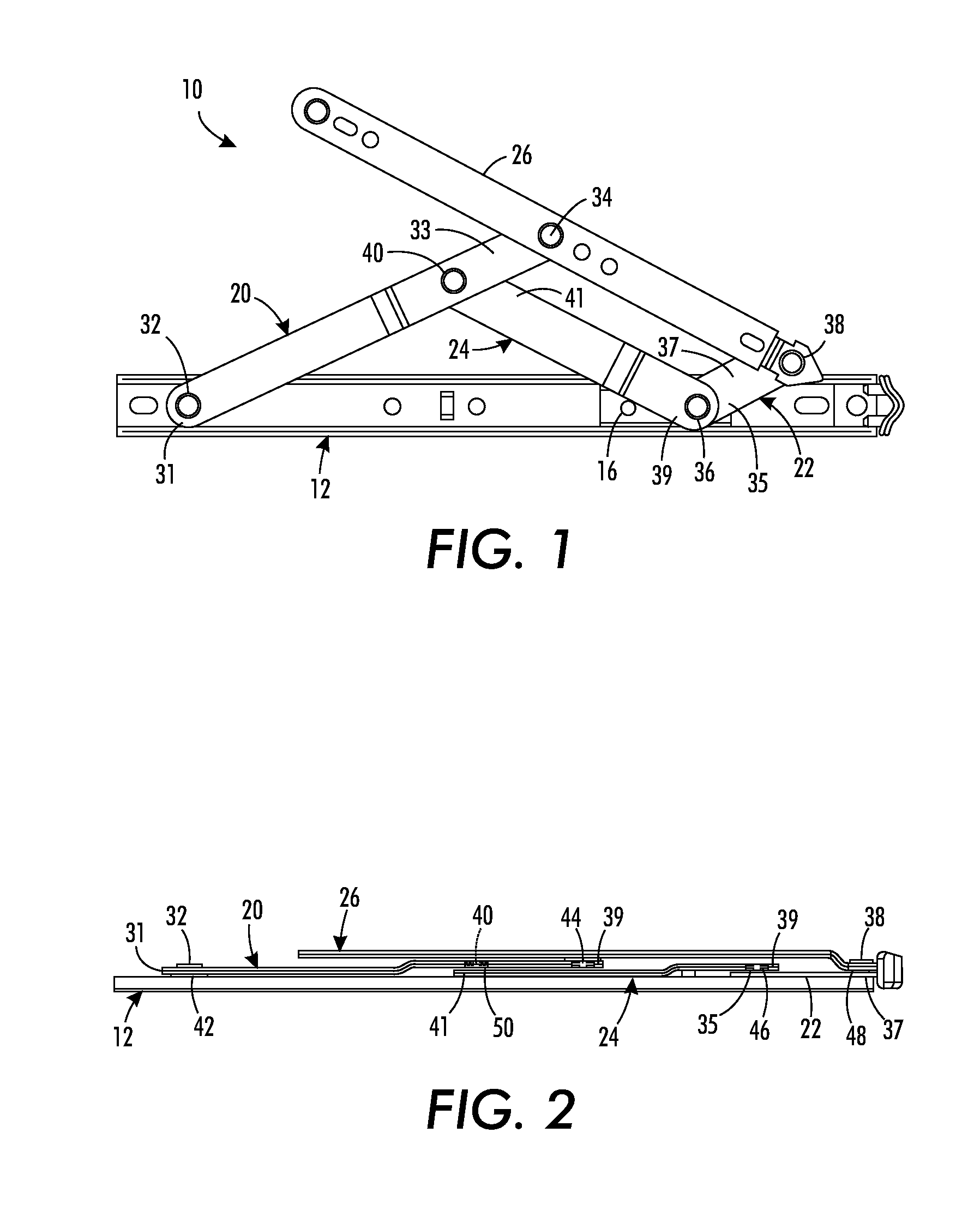
[0021]Referring to the drawing figures and in particular to FIG. 1, a 4-bar linkage assembly 10 of the type contemplated by this invention, includes a track 12 having a channel 14 along which a shoe 16 is guided for translation (i.e., slides) along a limited length of the channel 14. Intermediate linkage bars 20, 22, and 24 connect the track 12 to a vent bar 26. The shoe 16 is preferably made out of brass together with a resin friction-adjusting pad, but all of the linkages including the track 12, the vent bar 26, and the intermediate linkage bars 20, 22, and 24 are preferably made of stainless steel. The choice of materials can be made in accordance with requirements of the design and is not a limitation of the invention.

[0022]Intermediate linkage bar 20 has a first end 31 that is attached by way of a pivot pin 32 to the track 12 and a second end 33 that is attached by way of a pivot pin 34 to the vent bar 26. Similarly, the intermediate linkage bar 22 has a first end 35 that is at...


PUM


Abstract

A 4-bar linkage assembly for mounting a sash to a frame member of a window assembly. The linkage assembly including a vent bar having an offset portion and a base portion that fits within a sash channel of the sash. The vent bar includes a fixed connection extending between the offset portion and the base portion for supporting the offset portion and projecting between overhanging rails of the sash channel. The offset portion forms a stop which engages an end of the sash channel for locating the vent bar within the sash channel.

Description

TECHNICAL FIELD[0001]Within the field of window hardware, the invention relates to linkage assemblies for pivotally mounting sashes within frames and, more particularly, to adapting 4-bar linkage assemblies to the constraints of conventional channel mounts for anchoring hardware components.BACKGROUND OF INVENTION[0002]A standardized mounting system for attaching window hardware and accessory options to sashes and frames of window assemblies features elongated channels referred to as “Euro-Grooves”. The channels have a T-shaped cross section, comprising a channel bottom and two sidewalls with overhanging rails. Hardware can be slid along the channels to desired positions and anchored to the overhanging rails of the sidewalls.[0003]Although many benefits accrue from such standardized mounting systems, the channels can impose clearance limitations, particularly for linkages that support pivotal and translational motions of casement windows. For example, such channels can provide strong...

Claims


Application Information

Patent Timeline
Patent Type & Authority Patents(United States)
IPC IPC(8): E05F11/28
CPCE05D15/44E05D15/30E05D5/0238E05Y2900/148
Inventor MUIR, MALCOLM
Owner CALDWELL MFG NORTH AMERICA
Why Eureka
Try Eureka