Method and apparatus for manufacturing fuel pump

Active Publication Date: 2008-07-24
DENSO CORP
View PDF7 Cites 7 Cited by
  • Summary
  • Abstract
  • Description
  • Claims
  • Application Information

AI Technical Summary

Benefits of technology

[0010]The present invention addresses the above disadvantages. Therefore, it is an objective of the present invention to provide a manufacturing method and a manufacturing apparatus for an improved fu

Problems solved by technology

Thus, it is not possible to control the clearance with the high degree of precision, and thereby the deterioration in the fuel flow characteristics in the fuel pump is inevitable.

Method used


Image

  • Method and apparatus for manufacturing fuel pump
  • Method and apparatus for manufacturing fuel pump
  • Method and apparatus for manufacturing fuel pump

Examples


first embodiment

[0038]A manufacturing method and a manufacturing apparatus for manufacturing a fuel pump according to a first embodiment of the present invention will be described with reference to FIGS. 1A to 10.

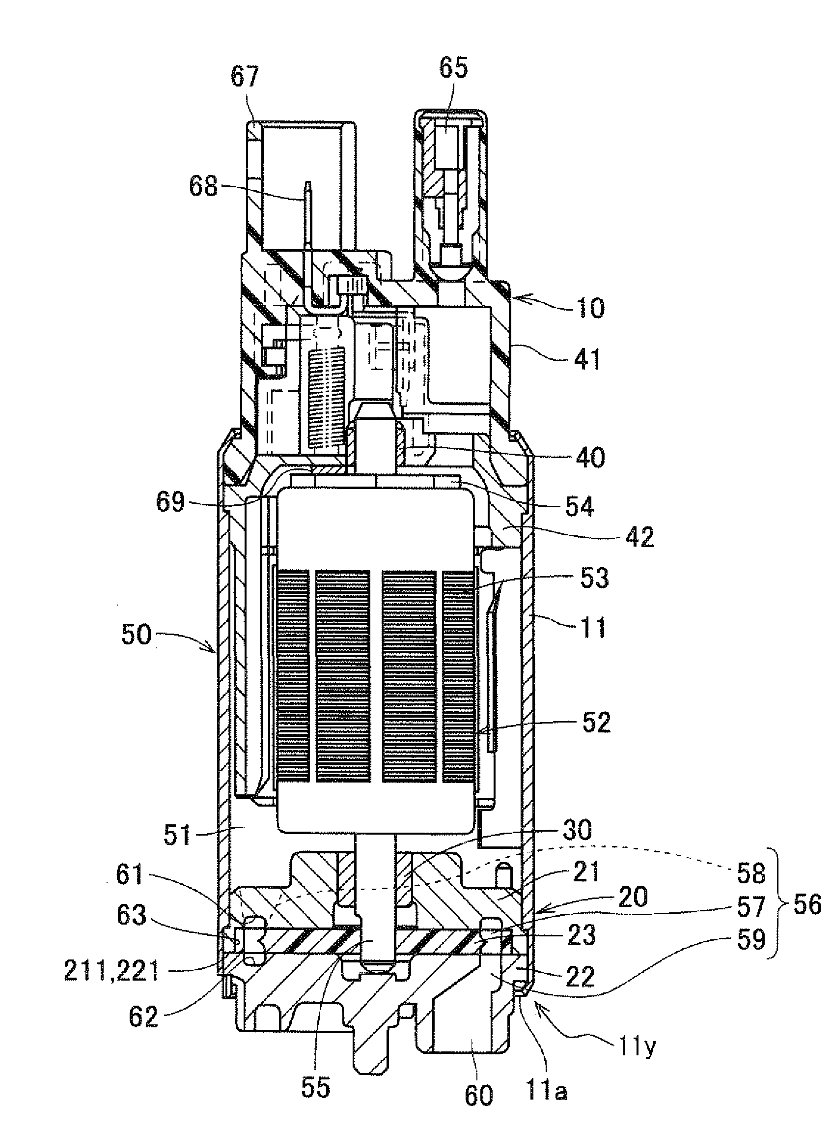
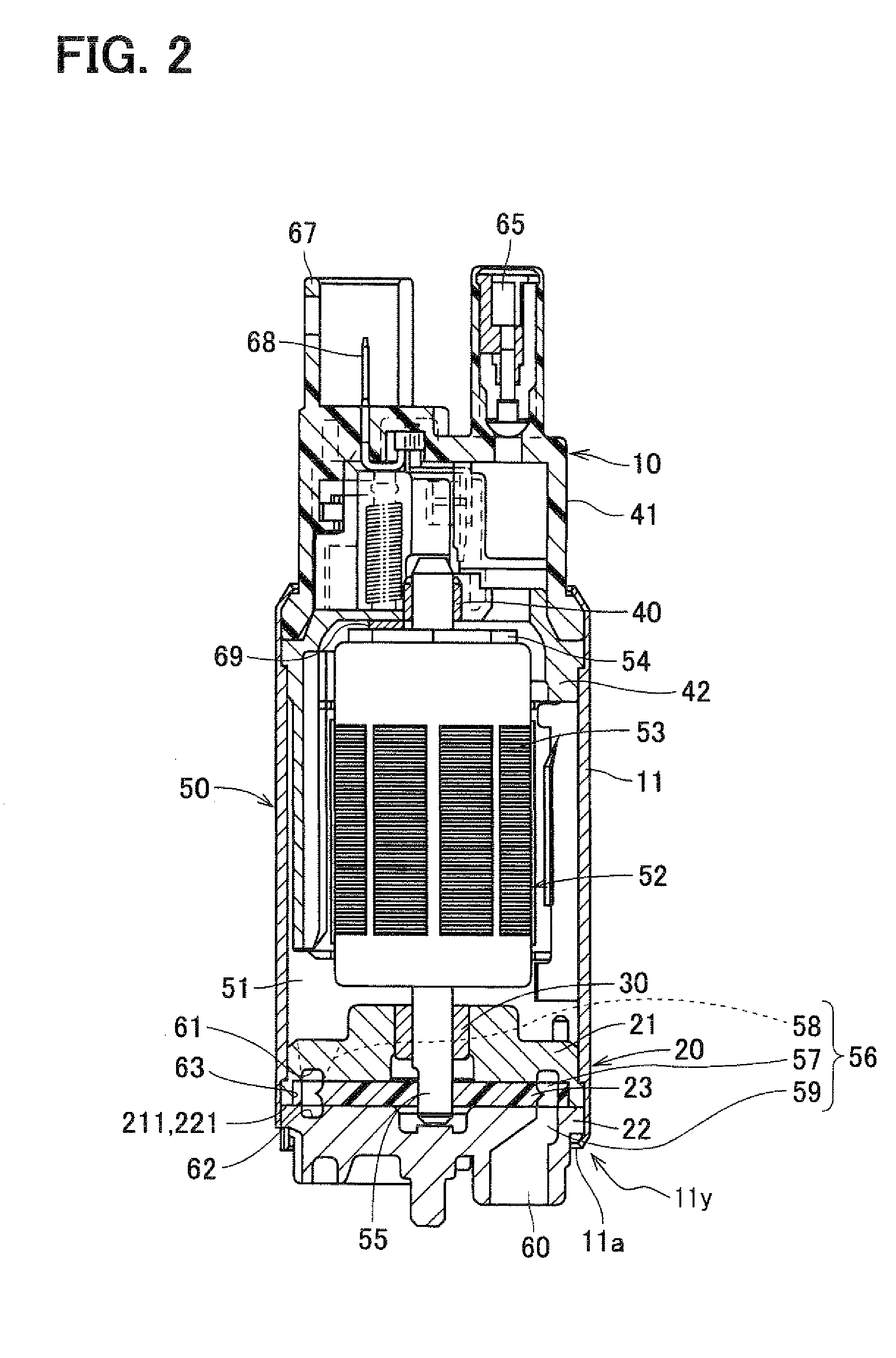
[0039]First, with reference to FIG. 2, an overall structure of a fuel pump 10 will be described. In this instance, the fuel pump 10 is received in a fuel tank of, for example, a two or four wheel vehicle (not shown). The fuel pump 10 draws fuel out of the fuel tank and discharges it toward an engine of the vehicle.

[0040]The fuel pump 10 includes a pump arrangement 20 and a motor arrangement 50. The motor arrangement 50 drives the pump arrangement 20. The motor arrangement 50 is formed as a direct current motor. In the motor arrangement 50, permanent magnets are arranged along an inner peripheral surface of a housing 11, and an armature 52 is placed radially inward of the magnets in the housing 11 in coaxial with the magnets.

[0041]The pump arrangement 20 includes a casing 21, a cover 22 and...

second embodiment

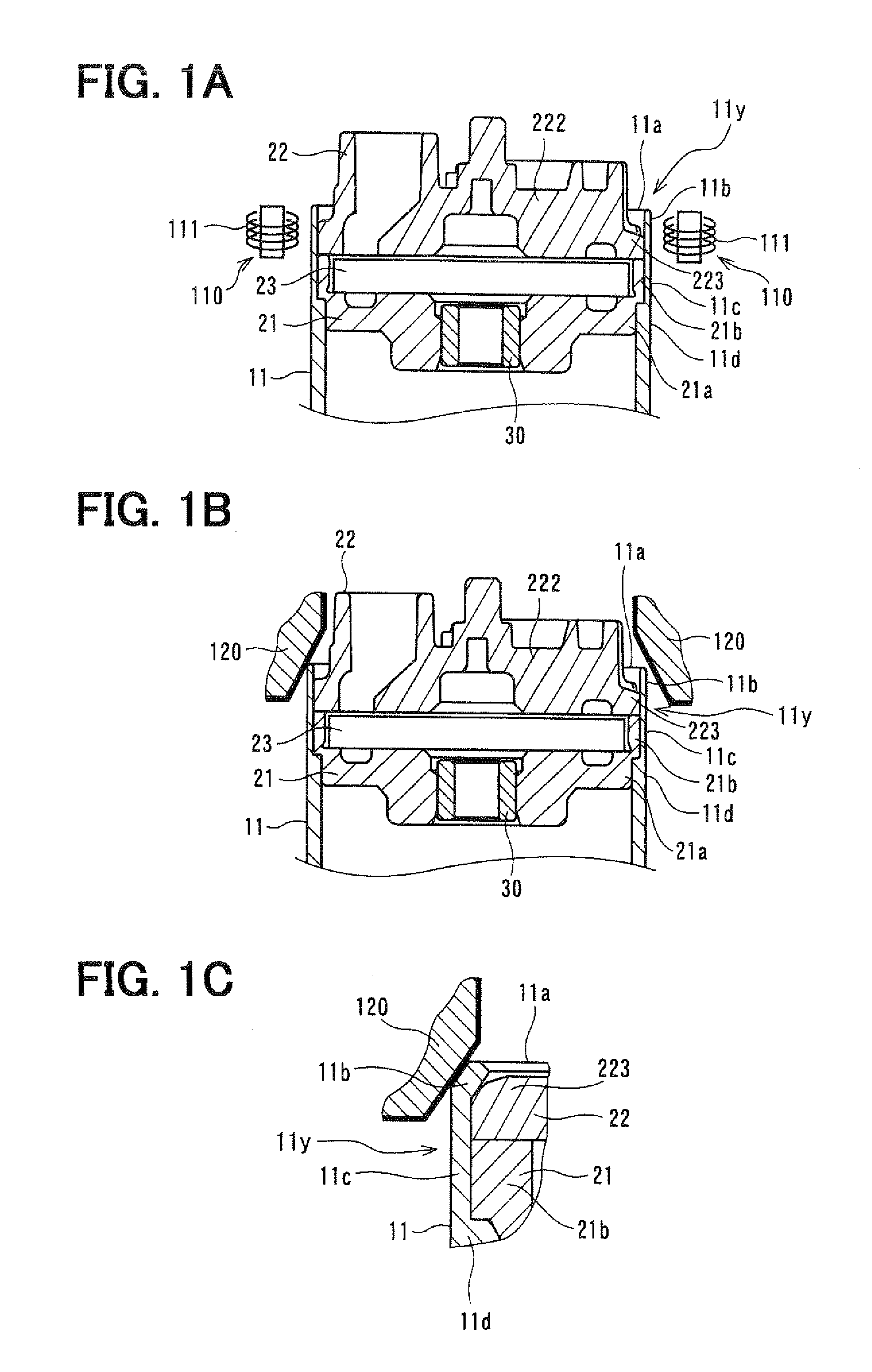
[0080]In a second embodiment of the present invention, after the bending portion 11b contacts the cover-side engaging portion 223, the punch 120 is moved downward until the bending portion 11b is pressed with a predetermined urging force in a resiliently deformable range. FIGS. 11A and 11B show a change in the axial force F1 in the manufacturing of the fuel pump and a change in the axial force F1 upon occurrence of a change in the environmental temperature.

[0081]Now, the change in the axial force F1 in the manufacturing of the fuel pump will be described.

[0082]First, during an assembling step shown in a section (A) in FIG. 11A, the casing 21 and the cover 22 are installed into the housing 11. Next, during a heating step shown in a section (B) in FIG. 11A, the housing-side engaging portion 11y of the housing 11 and therearound are temporarily heated by the electromagnetic induction heaters 110. In this way, the housing-side engaging portion 11y is elongated in the axial direction of ...

third embodiment

[0089]FIG. 13 shows a partial cross sectional view of a fuel pump manufactured according to a third embodiment of the present invention. The bending portion 11b of the housing 11 shown in FIG. 13 is a modification of the bending portion 11b of the fuel pump, which is formed by the manufacturing method of the first embodiment.

[0090]As shown in FIG. 12, the bending portion 11b of the fuel pump, which is formed by the manufacturing method of the first embodiment, has a linear cross section in a plane parallel to the axis of the housing 11. In contrast, the bending portion 11b of the housing 11 shown in FIG. 13 has a curved cross section in the plane parallel to the axis of the housing 11. When the shape of the bending portion 11b is adapted to conform with the shape of the cover-side engaging portion 223 of the cover 22, the removal of the cover 22 from the housing 11 can be further limited.


PUM


Abstract

A cover is inserted into a housing of a fuel pump. Then, a housing-side engaging portion of the housing, which is located at a peripheral edge of an opening of the housing, is heated with a heating means. Thereafter, the housing-side engaging portion is swaged by a punch toward the cover to fix the cover to the housing.

Description

CROSS REFERENCE TO RELATED APPLICATION[0001]This application is based on and incorporates herein by reference Japanese Patent Application No. 2007=12701 filed on Jan. 23, 2007 and Japanese Patent Application No. 2007-220855 filed on Aug. 28, 2007.BACKGROUND OF THE INVENTION[0002]1. Field of the Invention[0003]The present invention relates to a method and an apparatus for manufacturing a fuel pump.[0004]2. Description of Related Art[0005]With reference to FIG. 20, a known fuel pump includes a tubular housing 11, an impeller (not shown) and a cover 22. The housing 11 has an opening 11a and receives the impeller, and the cover 22 covers the opening 11a of the housing 11. The impeller is received in a pump chamber 22a, which is formed on one axial side of the cover 22 that is opposite from the opening 11a of the housing 11. In a case of the fuel pump recited in Japanese Unexamined Patent Publication 2005-207320 (corresponding to US2005 / 0163605A1), a housing-side engaging portion 11y, wh...

Claims


Application Information

Patent Timeline
IPC IPC(8): B23P15/00
CPCF02M37/048F04D5/002F04D29/406F04D29/605F04D29/628Y10T29/49238Y10T29/49918Y10T29/49229Y10T29/49917Y10T29/49236Y10T29/49915Y10T29/49925F05D2260/36
Inventor SAKAI, HIROMIUEDA, SHINJIHAZAMA, TADASHIIWANARI, EIJIWATANABE, SHOUYA
Owner DENSO CORP
Why Eureka
Try Eureka