

Member mounting method and mounting device
An installation method and installation device technology, applied in the direction of assembling printed circuits, electrical components, and electrical components with electrical components, can solve problems such as inability to control with high precision, differences, etc., and achieve the effect of high-precision control and installation of gaps between components
- Summary
- Abstract
- Description
- Claims
- Application Information
AI Technical Summary
Problems solved by technology
Method used
Image

Examples
no. 1 approach
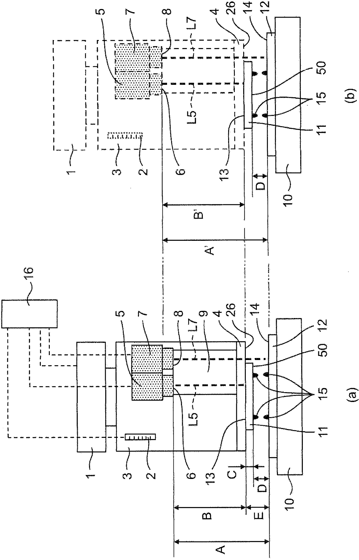
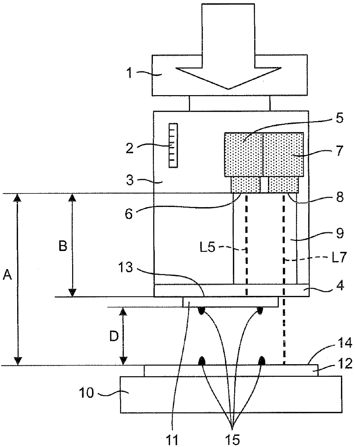
[0053] figure 1 (a) is a schematic diagram which shows the structure of the component mounting apparatus which concerns on 1st Embodiment of this invention at normal temperature.
[0054] The component mounting apparatus according to the first embodiment of the present invention includes: a table 10 that fixes a substrate 12 on which a bonding member 15 is formed; A glass adsorption tool 4 as an example of a suction tool; a mounting head 3 equipped with the glass suction tool 4 at the lower end; a Z-axis drive mechanism 1 as an example of a lifting drive device for driving the mounting head 3; A control device 16 for the drive of the shaft drive mechanism 1 .
[0055] The mounting head 3 includes a displacement measuring mechanism 2 that measures the displacement of the mounting head 3 in the Z-axis direction (vertical direction). The displacement measuring mechanism 2 is, for example, an optical laser encoder or a linear sensor. When it is outside the detectable distance ...
no. 2 approach
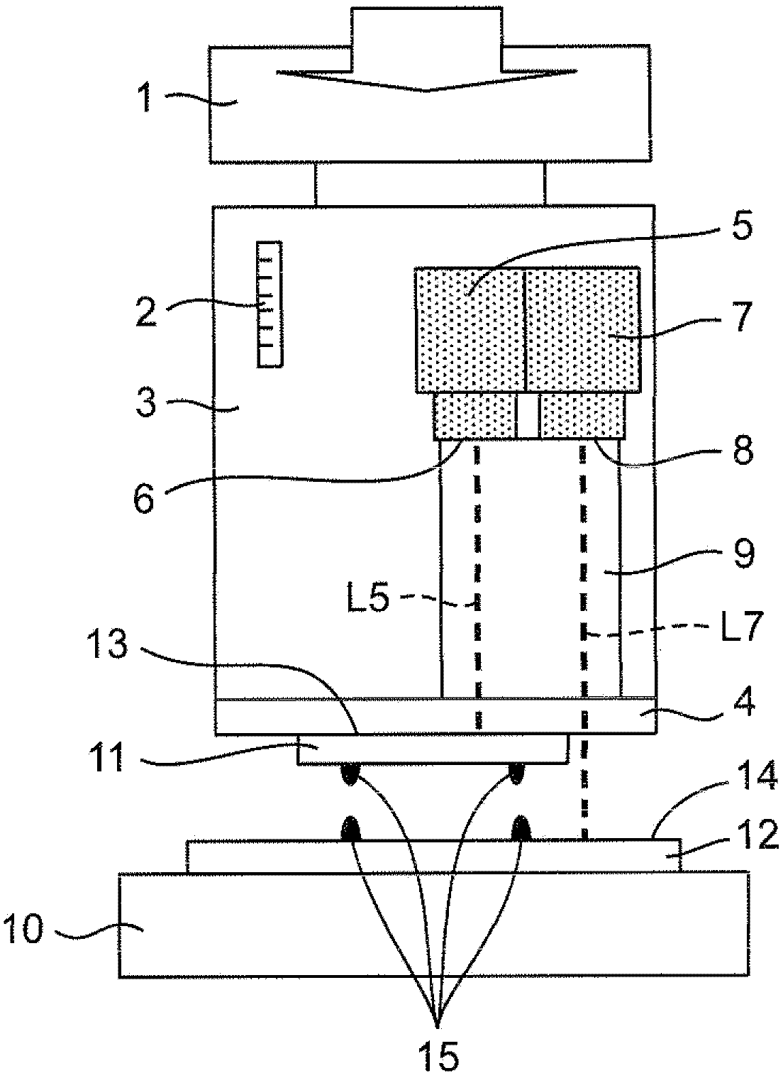
[0081] use image 3 , and the configuration of a component mounting apparatus as a second embodiment of the present invention will be described. The second embodiment is different from the first embodiment in the mounting member.
[0082] The structure of the inter-member gap D in the case where the measurement light L5 of the first non-contact optical distance measuring unit 5 passes through the mounting member 11 in the thickness direction and the distance from the first detection surface 6 to the lower surface 50 of the mounting member 11 can be measured will be described. Calculation method. The case where the measurement light L5 of the first non-contact optical distance measuring unit 5 passes through the mounting member 11 refers to, for example, the case where the mounting member 11 is made of glass and transmits the measurement light L5 of the first non-contact optical distance measuring unit 5, or the case where When the member 11 is a silicon chip and the waveleng...
no. 3 approach
[0089] use Figure 4A and Figure 4B , the configuration of the component mounting apparatus as the third embodiment will be described. The third embodiment is different from the first embodiment in the non-contact optical distance measurement unit. Figure 4A A configuration is shown in which a spectroscopic interference type laser displacement meter 21 , a detection surface 22 , and a cavity 9 are arranged so that laser light (measurement light) L21 does not pass through the mounting member 11 . Figure 4B A structure in which a spectroscopic interference type laser displacement meter 21 , a detection surface 22 , and a cavity 9 are arranged such that laser light (measurement light) L21 passes through the mounting member 11 is shown.
[0090] The first non-contact optical distance measuring unit 5 and the second non-contact optical distance measuring unit 7 in the first embodiment and the second embodiment, in the third embodiment, one non-contact optical distance measurin...
PUM
 Abstract
Description
Claims
Application Information