Perforated turbine bucket tip cover

a turbine and tip cover technology, applied in the field of turbine blade tip cover, can solve the problems of reducing the efficiency of the stage, increasing the backpressure, and increasing the size of the elevated tip votex, and achieve the effect of restricting the leakage flow

Inactive Publication Date: 2013-10-03
GENERAL ELECTRIC CO
View PDF4 Cites 7 Cited by
  • Summary
  • Abstract
  • Description
  • Claims
  • Application Information

AI Technical Summary

Benefits of technology

[0008]The top surface is configured to permit the blade to rotate with a limited clearance to a shroud of a casing of the turbine engine. A thickness of the tip cover extends from the top surface to a tip of the blade. A plurality of depressions are provided over essentially the full top surface of the tip. The depressions extend into the thickness of the tip cover and are adapted to restrict leakage flow between the tip cover and the shroud of the casing of the turbine engine.
[0009]According to another aspect of the present invention, a method is provided for fabricating a blade for a turbine engine. The method includes providing a blade including a tip cover with a top surface extending between a tip-cover pressure sidewall and a tip-cover suction sidewall, a first interlocking end at a trailing edge of the rotor blade and a second interlocking end at a leading edge of the rotor blade, and a thickness of the tip cover extending radially from the top surface of the tip cover to the rotor blade. The method includes removing a portion of the thickness of the tip cover forming a plurality of depressions over essentially the full top surface of the tip cover, the plurality of depressions being adapted to restrict leakage flow between the tip cover and the shroud of the casing of the turbine engine.

Problems solved by technology

Tip leakage may further result in elevated tip votex size and intensity, which may penetrate the main steam flow path downstream from the blade, raising backpressure and thereby lowering the efficiency of the stage.
While the purpose of the shroud is to seal the working fluid within the flow path as well as to provide a means to dampen vibrations, the shroud has its disadvantages as well.
A drawback to the shroud concept is the weight the shroud adds to the turbine blade.
Excessive loading on the blade root and disk can reduce the overall life of each component.
Another drawback to shrouds is creep curling of the blade shrouds.
Depending on the thickness of the shroud, the shroud edges can “curl” up at their ends and introduce severe bending stresses in the fillets between the shroud and blade tip.
The downside to simply increasing the shroud thickness uniformly is the additional weight that is added to the shroud by this additional material.
According to recent computational flow dynamic (CFD) analysis of 48″ last stage bucket of a low pressure turbine, adding a seal tooth may reduce the stage efficiency by about 0.5% since increased bucket tip volume can cause tip vortex to penetrate deeper into main flow.

Method used


Image

  • Perforated turbine bucket tip cover
  • Perforated turbine bucket tip cover
  • Perforated turbine bucket tip cover

Examples


Embodiment Construction

[0020]The following embodiments of the present invention have many advantages, including reducing bucket tip leakage flow, increasing rotor torque work, minimizing mixing losses caused by tip vortex, improving turbine performance and reducing tip cover weight.

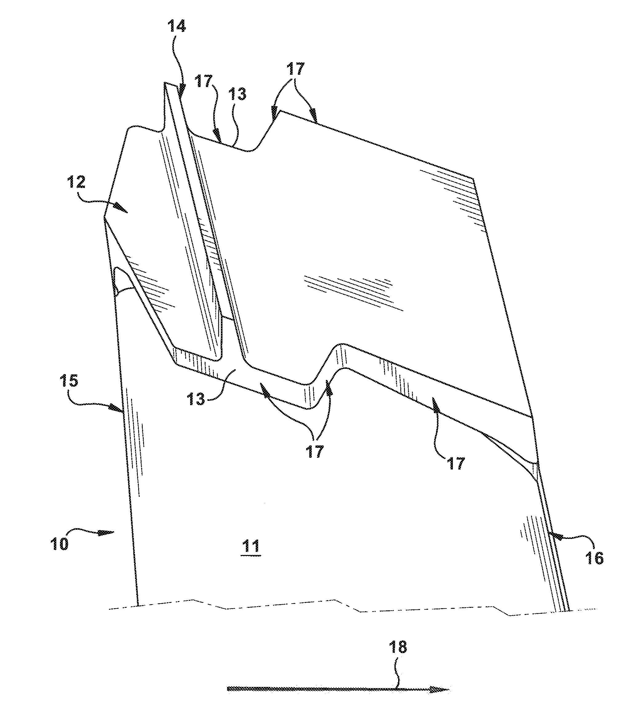
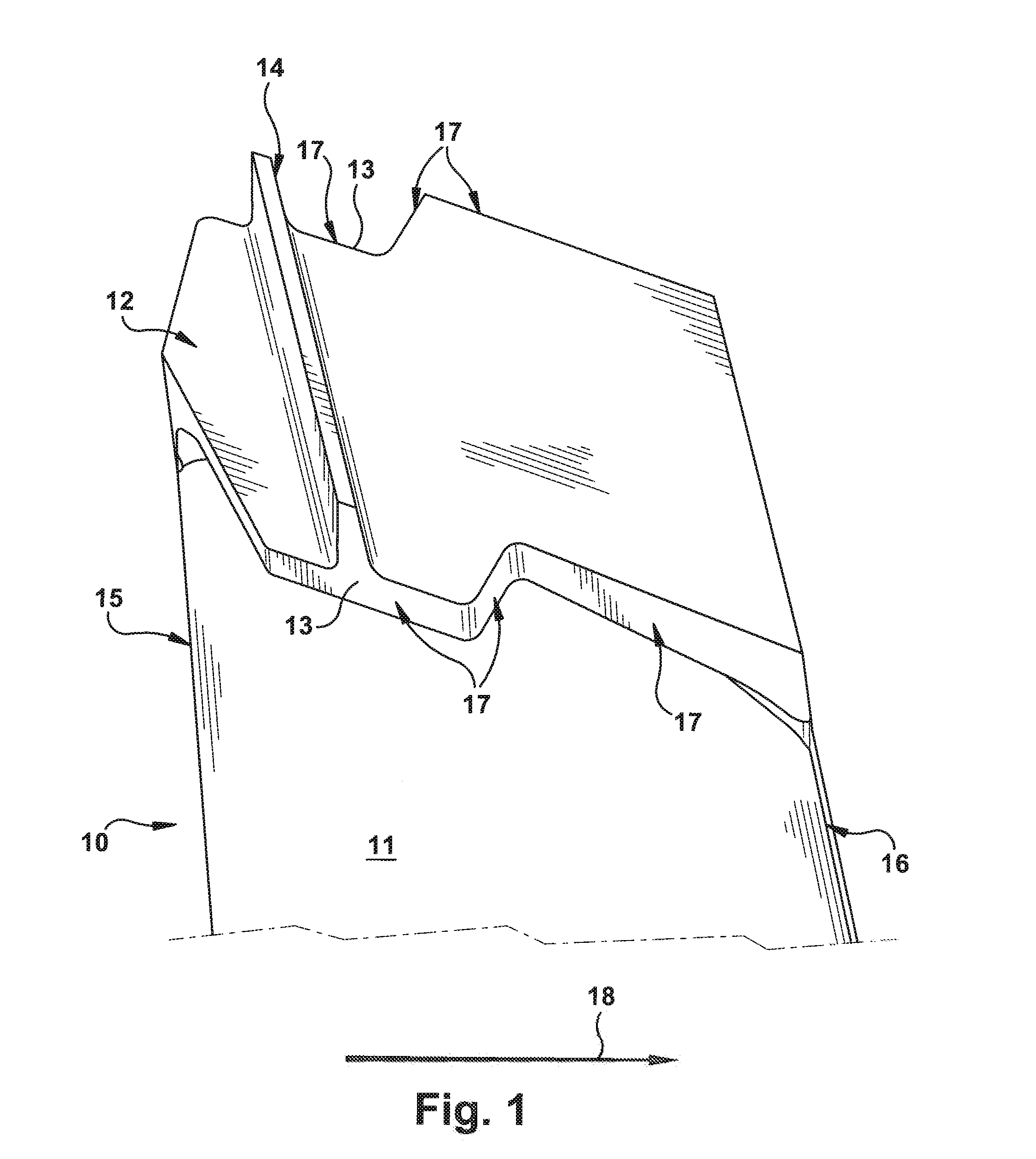
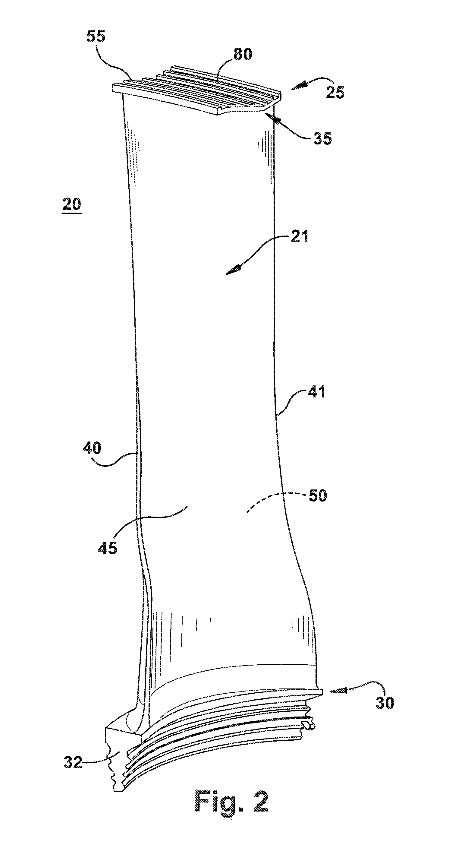
[0021]The present invention relates to an airfoil with a tip cover surface treatment for reducing leakage flows, minimizing tip vortex size and penetration into main flow that will improve turbine efficiency. An aspect of the present invention is to treat airfoil tip covers with a series of concave shapes, such as grooves or holes. These grooves and holes will cause the leakage flow into separate flow paths within the cavities and generate more resistance to leakage flows through the airfoil tip clearance, that reduces the leakage mass flow and weakens tip vortex and its interaction with turbine main flows. The material removed from the tip cover provides the additional benefit of reducing the weight of the tip cover, thereby e...


PUM

PropertyMeasurementUnit
pressureaaaaaaaaaa
thicknessaaaaaaaaaa
speedaaaaaaaaaa

Abstract

An airfoil with a tip cover surface treatment for reducing leakage flows, minimizing tip vortex size and penetration into main flow that will improve turbine efficiency. The surface treatment for the airfoil tip covers includes a series of concave shapes, such as grooves or holes. These grooves and holes will cause the leakage flow into separate flow paths within the cavities and generate more resistance to leakage flows through the airfoil tip clearance, thereby reducing the leakage mass flow and weakening tip vortex and its interaction with turbine main flows. The material removed from the tip cover provides the additional benefit of reducing the weight of the tip cover, thereby enhancing blade reliability.

Description

BACKGROUND OF THE INVENTION[0001]The invention relates generally to turbine blades for a turbine engine and more specifically to a tip shroud for turbine blades.[0002]Turbine blades are rotating airfoil-shaped components in series of stages designed to convert thermal energy from a working fluid, such as gas or steam, into mechanical work of turning a rotor. Performance of a turbine can be enhanced by sealing the outer edge of the blade tip to prevent the working gas from escaping the working flowpath into the gaps between a blade tip and an outer casing of turbine. A common manner for sealing the gap between the turbine blade tips and the turbine casing is through blade tip shrouds. Not only do shrouds enhance turbine performance, but also serve as a vibration damper, especially for large, radial-length turbine blades. The shroud acts as a mechanism to raise the blade natural frequency and in turn minimizes failures due to extended resonance time of the blade at a natural frequency...

Claims


Application Information

Patent Timeline
Patent Type & Authority Applications(United States)
IPC IPC(8): F01D5/22
CPCF01D5/225Y10T29/49336F05D2260/2212F01D5/22
Inventor LIU, XIAOYUECOTRONEO, JOSEPH A.SLEPSKI, JONATHON E.CEYLAN, ZEKAIMISTRY, HITESHKUMAR R.
Owner GENERAL ELECTRIC CO
Why Eureka
Try Eureka