Hydrostatic transaxle

a transaxle and hydrostatic technology, applied in the direction of fluid couplings, gearings, couplings, etc., can solve the problems of increased components and costs, complex piping or mechanisms, inconvenience for assembly and maintenance, etc., and achieves simple and inexpensive disposal, large ground clearance, and large space

Active Publication Date: 2010-04-06
KANZAKI KOKYUKOKI MFG
View PDF10 Cites 18 Cited by
  • Summary
  • Abstract
  • Description
  • Claims
  • Application Information

AI Technical Summary

Benefits of technology

[0008]Therefore, in comparison with the tie rod provided to the conventional hydrostatic transaxle, the pair of connection rods are easily extended forward or rearward from the steering arms so that utmost ends of the respective connection rods can be spaced forward or rearward from the hydrostatic transaxle so as to be connected to the common rotary member of the steering operation mechanism. Consequently, a sufficiently large space near the hydrostatic transaxle outside of the tie-rod arrangement space can be ensured so as to compactly and simply arrange other components near the hydraulic transaxle, thereby reducing the components in number and cost, and facilitating assembly and maintenance.
[0010]In this regard, the two-motor type hydrostatic transaxle, including the pair of hydraulic motors, advantageously drives the respective left and right axles individually so as to have excellent turnability and traveling performance. While this effect is obtained, the above-mentioned large space near the hydrostatic transaxle obtained by the arrangement of the pair of connection rods can advantageously involve several components required for constituting the two-motor type hydrostatic transaxle.
[0012]Therefore, during turn of a vehicle equipped with the hydrostatic transaxle, the steerable drive wheels supported by the steerable wheel support units of the hydrostatic transaxle have a different rotary speed from that of unsteerable drive wheels of the vehicle, thereby preventing dragging of the steerable drive wheels or the unsteerable drive wheels.
[0013]Preferably, the motor casing and the pair of steerable wheel support units are arranged in a gate-shape in a front or rear view by offsetting the axles downward from the at least one output shaft. Therefore, a power transmission component (e.g., a pressure fluid pipe and / or a propeller shaft) and / or other components can be simply and inexpensively disposed in a sufficiently large space ensured below the motor casing between the steerable wheel support units so as to be prevented from interfering with the connection rods and components of the steering operation mechanism. Further, the gate-shape of the hydrostatic transaxle ensures a large ground clearance advantageously for traveling of an agriculture tractor over a ridge, for instance.
[0015]Preferably, the steering arms of the respective steerable wheel support units include respective portions to which a pair of connection rods are connected, and wherein the pair of connection rods are extended and connected to the common rotary member of the steerable operation mechanism so as to be arranged in a V-shape. Therefore, the common rotary member is effectively spaced from the hydraulic transaxle so as to ensure a large space surrounded by the connection rods and the rotary member in front or rear of the transaxle, thereby facilitating arrangement of various components.

Problems solved by technology

That is, these members and devices surrounding the hydrostatic transaxle cannot be compactly arranged near the hydrostatic transaxle, thereby resulting in complex piping or mechanism, increased components and costs, inconvenience for assembly and maintenance, etc.

Method used


Image

  • Hydrostatic transaxle
  • Hydrostatic transaxle
  • Hydrostatic transaxle

Examples


Embodiment Construction

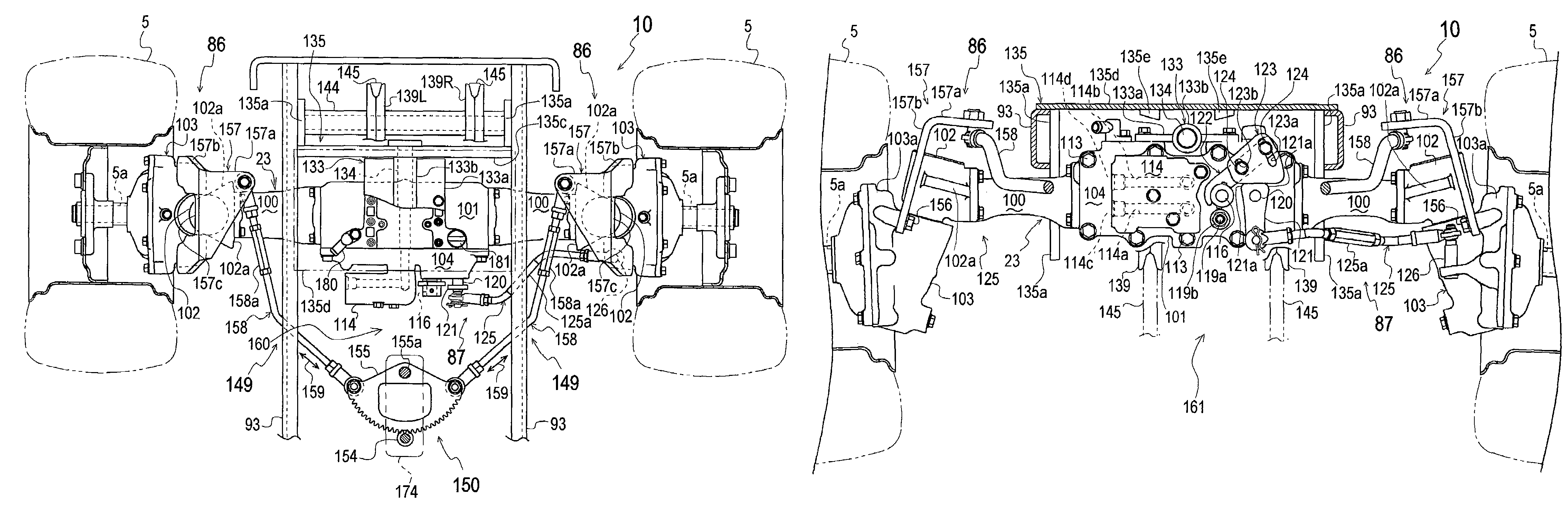
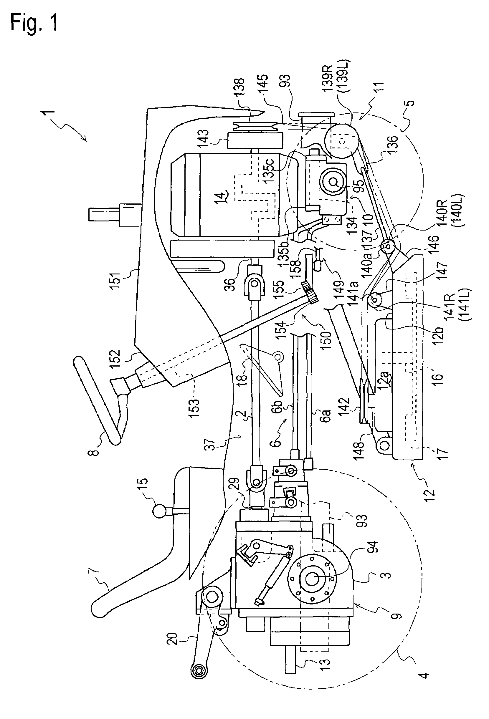
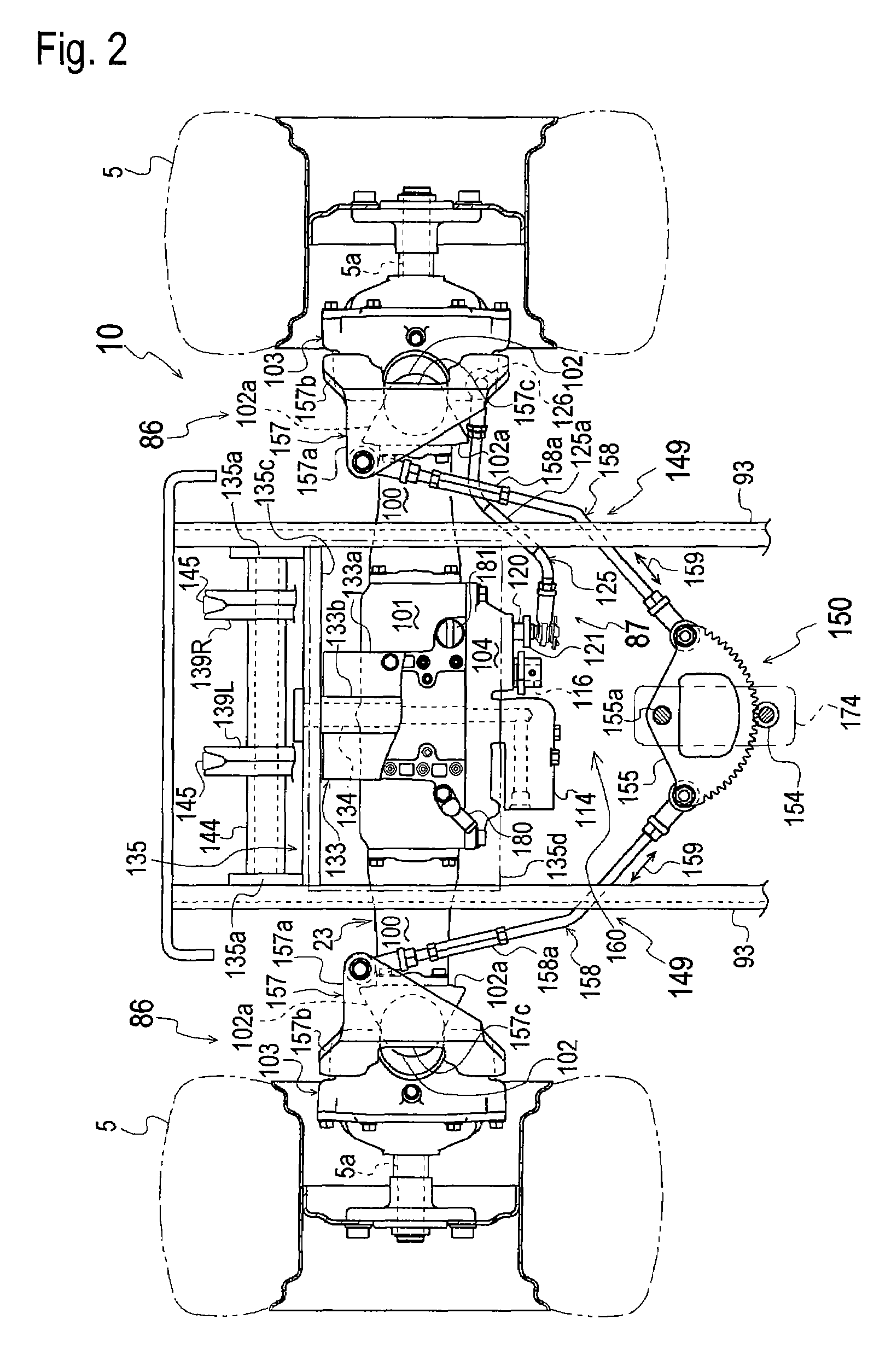
[0034]Referring to FIG. 1, description will be given of a general configuration of a working vehicle 1 serving as an embodiment of a working vehicle equipped with a hydrostatic transaxle of the invention. Working vehicle 1 includes a vehicle frame 93. An engine 14 is mounted on a front portion of vehicle frame 93, and a rear transaxle 9 including a casing 3 is supported by a rear portion of vehicle frame 93 between left and right rear unsteerable drive wheels 4. A power transmission linkage 37 is interposed between engine 14 and rear transaxle 9. In power transmission linkage 37, a propeller shaft 2 is interposed between a horizontal rearward projecting engine output shaft 36 of engine 14 and a horizontal forward projecting input shaft 29 of rear transaxle 9 through universal joints, preferably, so as to transmit power from engine 14 to rear transaxle 9. A front transaxle 10 is supported by the front portion of vehicle frame 93 below engine 14 so as to turn and drive left and right ...


PUM


Abstract

A hydrostatic transaxle comprises: a motor casing; at least one hydraulic motor disposed in the motor casing; at least one output shaft disposed in the motor casing so as to be driven by the at least one hydraulic motor; and a pair of steerable wheel support units attached onto respective opposite ends of the motor casing. Each of the steerable wheel support units includes an axle, a steerable casing, a wheel, and a steering arm. In each of the steerable wheel support units, the axle is drivingly connected to the at least one output shaft, the steerable casing is substantially horizontally rotatable relative to the motor casing, the wheel is attached on an outer end of the axle outside of the steerable casing, and the steering arm is rotatably integrally provided on the steerable casing. The hydrostatic transaxle further comprises a pair of connection rods for connecting the steering arms of the steerable wheel support units to a common rotary member of a steering operation mechanism spaced forward or rearward from the hydrostatic transaxle.

Description

BACKGROUND OF THE INVENTION[0001]1. Field of the Invention[0002]The invention relates to a hydrostatic transaxle including a motor casing incorporating a hydraulic motor for driving an axle drivingly connected to a pair of left and right steerable drive wheels, and a pair of steerable wheel support units attached onto opposite outer ends of the motor casing so as to steerably (i.e., horizontally rotatably) support the respective steerable drive wheels. Particularly, the invention relates to a structure of the hydrostatic transaxle adapted to a steering operation mechanism for turning the steerable drive wheels.[0003]2. Related Art[0004]There is a well-known conventional hydrostatic transaxle including a motor casing incorporating a hydraulic motor for driving an axle drivingly connected to a pair of left and right steerable drive wheels, wherein a pair of left and right steerable wheel support units are attached onto opposite outer ends of the motor casing so as to steerably support...

Claims


Application Information

Patent Timeline
Patent Type & Authority Patents(United States)
IPC IPC(8): B60K17/30
CPCB60K17/30B62D3/02B62D9/002B62D11/001B62D11/06B62D7/18B60K17/043B60Y2200/223F16H39/14
Inventor IWAKI, KOJIISHII, NORIHIROISHINO, FUMITOSHI
Owner KANZAKI KOKYUKOKI MFG
Why Eureka
Try Eureka