Position sensitive shock absorber

a technology of shock absorber and position, which is applied in the direction of shock absorber, steering device, cycle equipment, etc., can solve the problems of altering handling characteristics and being able to extend, and achieve the effect of altering the handling characteristics of an associated bicycl

Active Publication Date: 2010-04-06
SPECIALIZED BICYCLE COMPONENTS INC
View PDF27 Cites 23 Cited by
  • Summary
  • Abstract
  • Description
  • Claims
  • Application Information

AI Technical Summary

Benefits of technology

[0013]Accordingly, a need exists for a shock absorber configured to provide a desirable level of pedaling efficiency, while offering at least some amount of “sag”. That is, preferably, the shock absorber does not normally assume a fully extended, or topped out, position when a rider's weight is applied to the bicycle. Preferred embodiments of the present position sensitive shock absorber allow the shock absorber to move to a sag position, despite the inertia valve not being activated, to provide a desired ride height of the bicycle. In addition, preferably, the shock absorber becomes locked-out, or substantially locked-out, once the sag position is achieved by, for example, substantially preventing fluid flow in a compression direction within the shock absorber until the inertia valve is activated by an appropriate acceleration force. This feature is especially advantageous when the shock absorber is used with bicycles having relatively longer wheel suspension displacement, or “travel”, because the sag constitutes a larger proportion of the overall travel and is thus more easily noticed by the rider. The greater sag distance also changes other related geometries of the bicycle such as head tube angle and seat tube angle to a greater degree than that of relatively shorter travel bicycles. Thus, the benefits of the preferred position sensitive shock absorber system become more pronounced as the suspension travel increases. Furthermore, preferred embodiments of the position sensitive valve may be incorporated within suspension assemblies that do not include an acceleration sensitive inertia valve, but utilize pressure activated valves, or other mechanisms for creating a damping force.

Problems solved by technology

Thus, the tendency of the illustrated shock absorbers of U.S. Pat. No. 6,267,400 is to assume a fully extend position, or topped-out position and may alter the handling characteristics of an associated bicycle, especially when the bicycle frame geometry is not specifically designed for such a shock absorber.
Further, because the shock absorber is normally in a topped-out position, it may not be able to extend in the event that the surface upon which the bicycle is being ridden suddenly drops away from the bicycle wheel, such as in the situation of the bicycle encountering a drop-off or depression.

Method used


Image

  • Position sensitive shock absorber
  • Position sensitive shock absorber
  • Position sensitive shock absorber

Examples


Embodiment Construction

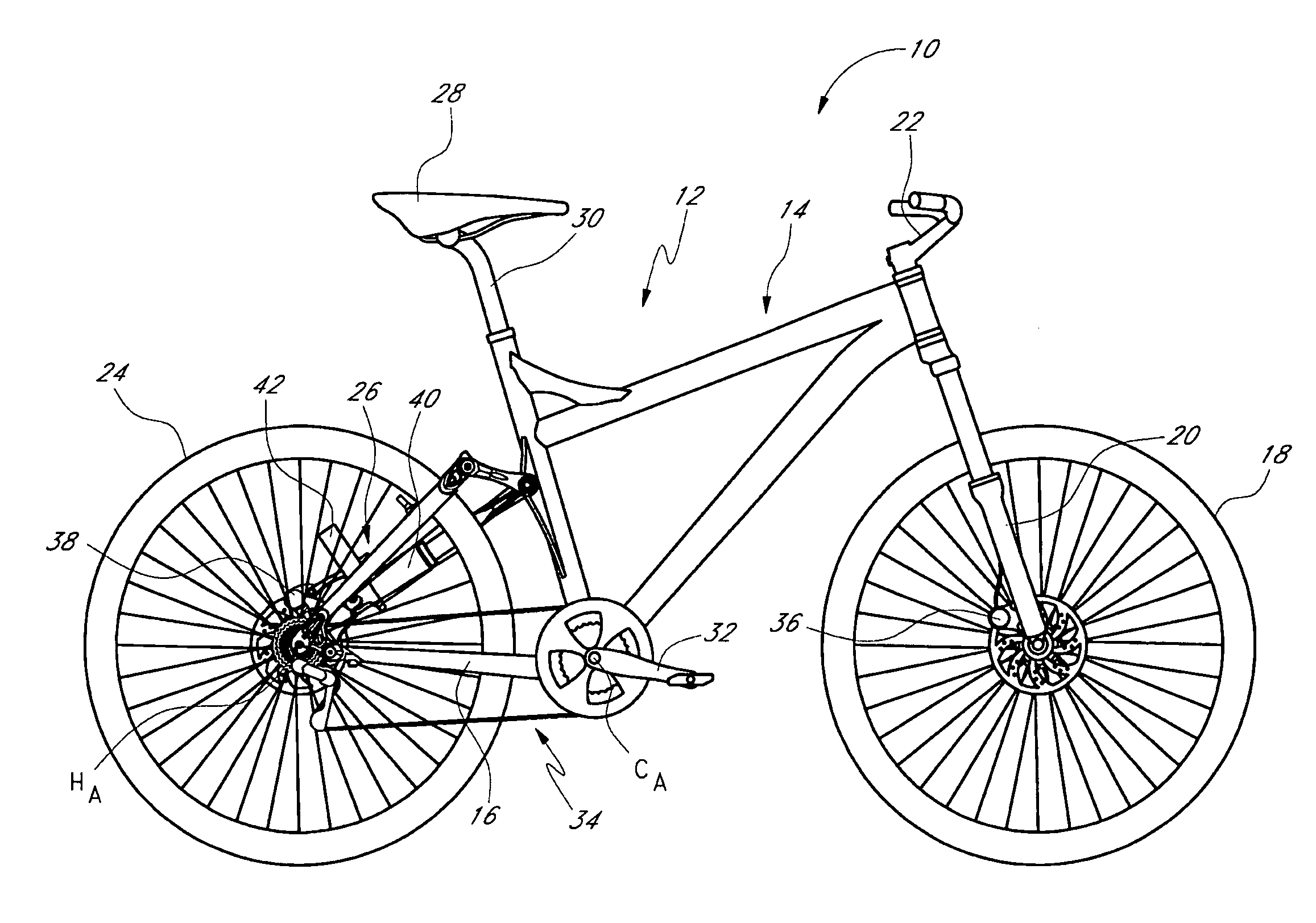
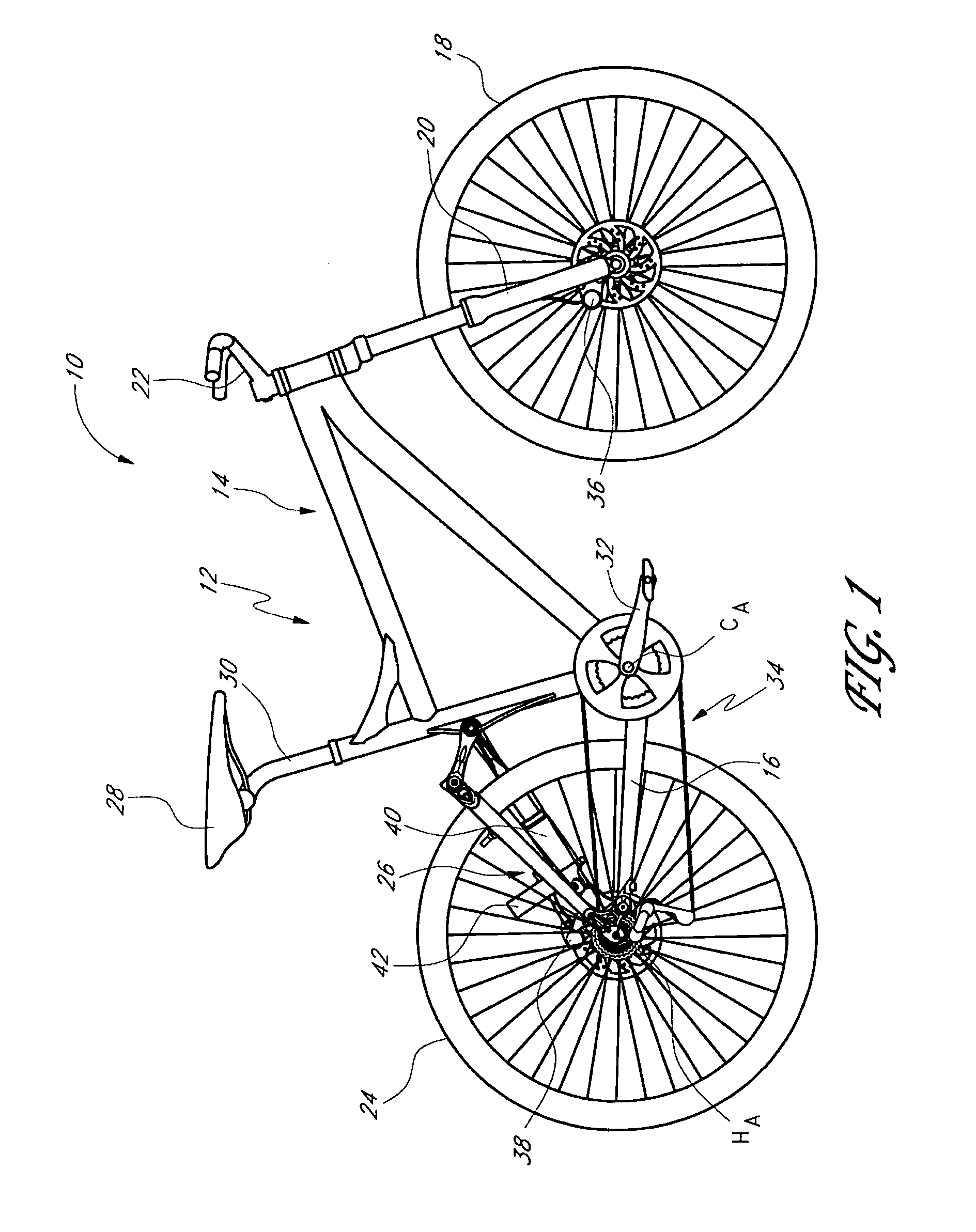
[0037]FIG. 1 illustrates an off-road bicycle, or mountain bike 10, including a preferred embodiment of a rear suspension assembly, or shock absorber. The bicycle 10 is described herein with reference to a coordinate system wherein a longitudinal axis extends from a forward end to a rearward end of the bicycle 10. A vertical, central plane generally bisects the bicycle 10 and contains the longitudinal axis. A lateral axis extends normal to the longitudinal axis and lies within a horizontal plane. In addition, relative heights are generally expressed as elevations relative to a horizontal surface on which the bicycle 10 is supported in an upright position. The above-described coordinate system is provided for the convenience of describing the bicycle illustrated in FIGS. 1 and 5, and is not intended to limit the scope of the present invention. In addition, certain features and components of the bicycle may be described in terms of relative positions or directions within the particular...


PUM


Abstract

A shock absorber includes a tube and a piston rod carrying a piston. The piston is configured for reciprocal movement within the tube. A floating piston, or other type of accumulator, is configured to move to accommodate fluid displaced due to successive portions of the piston rod entering the tube during compression of the shock absorber. The shock absorber includes a valve mechanism that utilizes the movement of the floating piston to move the valve between a first and second position, which preferably are open and closed positions.

Description

CROSS-REFERENCE TO RELATED APPLICATIONS[0001]This application is related to, and claims priority from, U.S. Provisional Patent Application No. 60 / 709,206, filed Aug. 18, 2005.INCORPORATION BY REFERENCE[0002]The entirety of U.S. Provisional Patent Application No. 60 / 709,206, filed Aug. 18, 2005, is expressly incorporated by reference herein and made a part of the present specification.BACKGROUND OF THE INVENTION[0003]1. Field of the Invention[0004]The present invention generally relates to vehicle suspension systems. More specifically, the present invention relates to an improved shock absorber system to be incorporated into the suspension system of a vehicle, such as a bicycle.[0005]2. Description of the Related Art[0006]Bicycles intended for off-road use, i.e., mountain bikes, commonly include a suspension assembly operably positioned between the front and / or rear wheels of the bicycle and the frame of the bicycle. The suspension assembly typically includes a shock absorber configu...

Claims


Application Information

Patent Timeline
Patent Type & Authority Patents(United States)
IPC IPC(8): B62K3/02F16F9/34
CPCB62K25/04B62K25/08B62K25/286F16F9/486F16F9/065F16F9/067F16F9/48B62K2025/048
Inventor MCANDREWS, MICHAEL
Owner SPECIALIZED BICYCLE COMPONENTS INC
Why Eureka
Try Eureka