Radar target detection method and radar apparatus using the same

a radar and target azimuth technology, applied in the field of radar target azimuth detection methods, can solve the problems of high manufacturing cost, inability to uniformly suppress the grating lobe of radar, and difficulty in changing the directivity pattern as necessary, so as to achieve accurate detection of the target azimuth, improve detection accuracy, and improve detection accuracy

Inactive Publication Date: 2010-04-06
MURATA MFG CO LTD
View PDF32 Cites 20 Cited by
  • Summary
  • Abstract
  • Description
  • Claims
  • Application Information

AI Technical Summary

Benefits of technology

[0011]In addition, the radar disclosed in Japanese Unexamined Patent Application Publication No. 2000-258524 realizes a plurality of antenna patterns by switching a relatively large number of antenna elements using a switch. Thus, in implementation of this radar, a large number of switches may be necessary, which results in high manufacturing cost.
[0034]Furthermore, switching of a plurality of directivity patterns enables accurate detection of the target azimuth even if no change occurs in the target azimuth with respect to the radar.

Problems solved by technology

However, it is difficult to change the directivity pattern as necessary.
Thus, this radar is not capable of uniformly suppressing grating lobes regardless of the azimuth of the target.
Thus, in implementation of this radar, a large number of switches may be necessary, which results in high manufacturing cost.
However, this radar is difficult to implement in terms of Radio Laws and manufacturing cost.

Method used


Image

  • Radar target detection method and radar apparatus using the same
  • Radar target detection method and radar apparatus using the same
  • Radar target detection method and radar apparatus using the same

Examples


first embodiment

[0043]In the following, a radar apparatus and a target detection method using the radar apparatus according to the present invention will be described with reference to the drawings. In this embodiment, the radar apparatus is assumed to be an FMCW (frequency modulated continuous wave) radar apparatus having a transmitting antenna composed of one antenna element and a receiving antenna composed on a plurality of antenna elements.

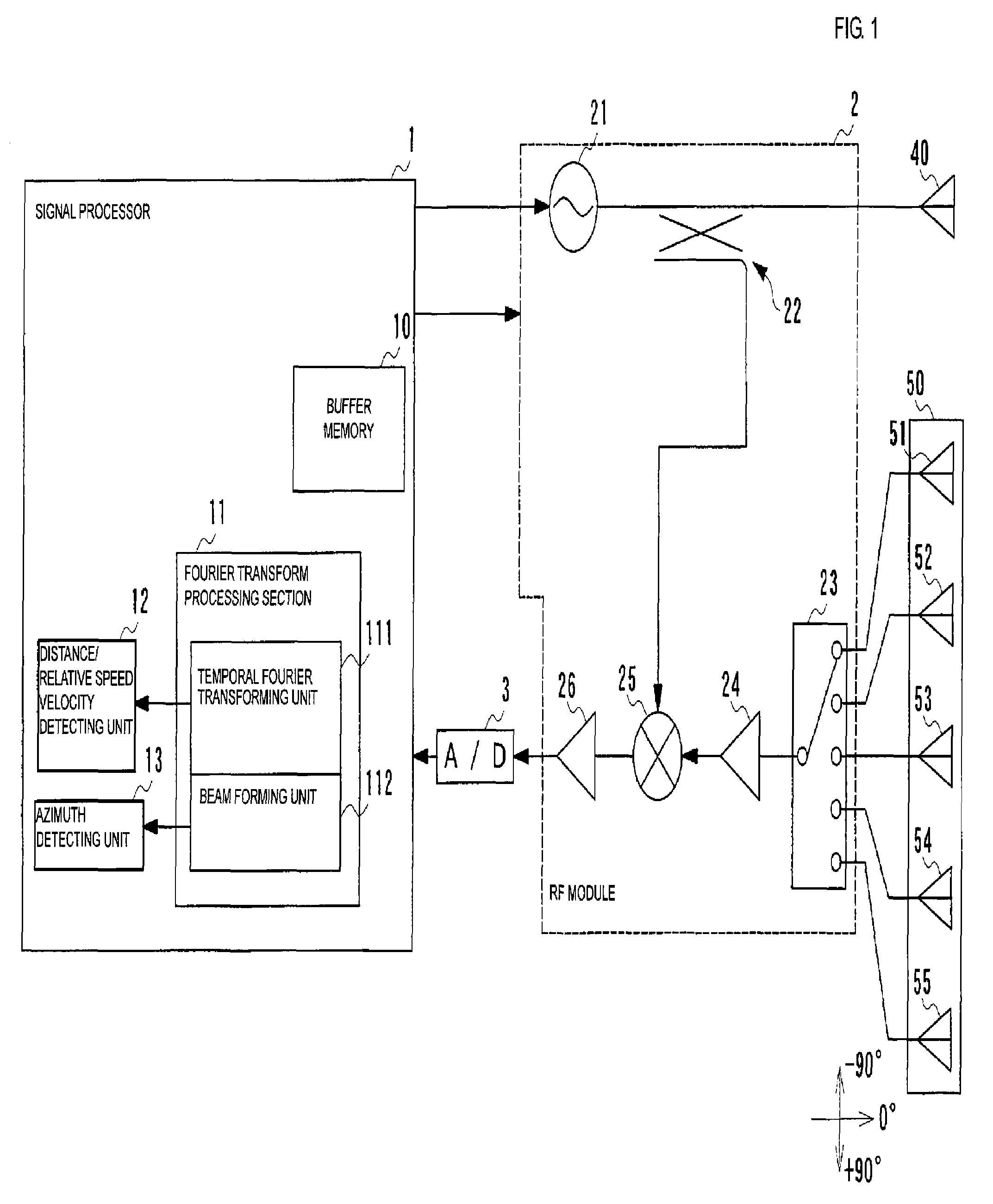
[0044]FIG. 1 is a block diagram schematically illustrating a configuration of an FMCW radar apparatus according to an embodiment of the present invention.

[0045]As illustrated in FIG. 1, the radar apparatus has a signal processor 1 performing transmission signal control, switching control, and object detection, an RF (radio frequency) module 2, a transmitting antenna 40 and a receiving antenna 50.

[0046]In control of a transmission system, the signal processor 1 generates a transmission control signal and a switching control signal. The transmission control sig...

second embodiment

[0087]In the following, a radar apparatus and a radar target detection method for the radar apparatus according to the present invention will be described with reference to the drawings.

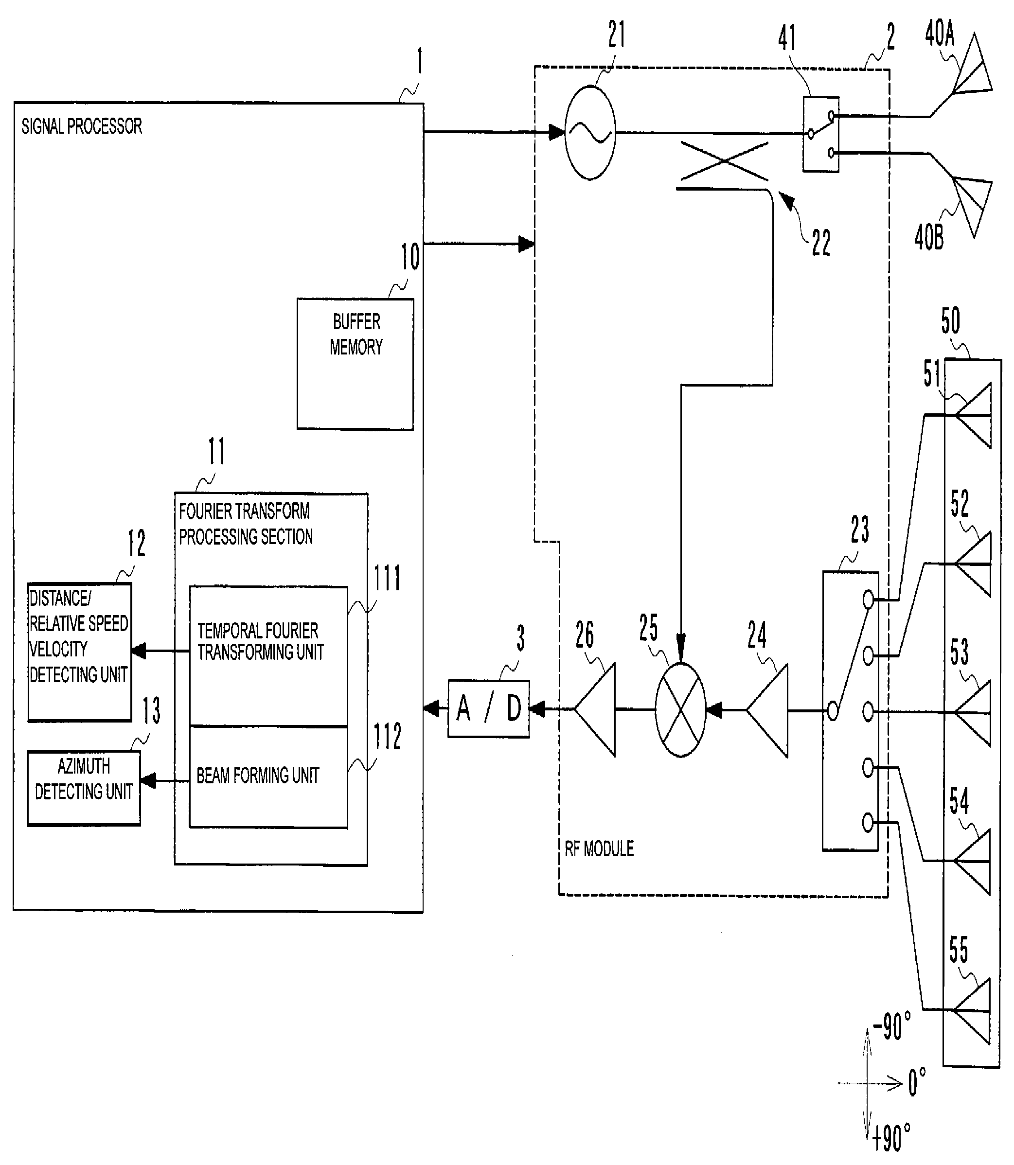
[0088]FIG. 6 is a block diagram illustrating a configuration of an FMCW radar apparatus according to an embodiment of the present invention.

[0089]Each of FIGS. 7A and 7B illustrates a locus of spectrum peaks levels in an azimuth spectrum and a directivity pattern. FIG. 7A illustrates a locus of spectrum peaks and a directivity pattern obtained at a transmitting antenna 40A, and FIG. 7B illustrates a locus of spectrum peaks and a directivity pattern obtained at a transmitting antenna 40B.

[0090]As illustrated in FIG. 6, the radar apparatus in this embodiment has two transmitting antennas 40A and 40B, and a switch circuit 41 for switching between the transmitting antennas 40A and 40B. The radar apparatus according to this embodiment and the radar apparatus according to the first embodiment are different...


PUM


Abstract

A radar target detection method in which an azimuth at which a target is located is detected on the basis of reception signals obtained through antenna elements of an array antenna by detecting a change in levels of spectrum peaks in an azimuth spectrum of reception signal intensities, calculating a level of correlation between the level change of each spectrum peak and a directivity pattern of the array antenna in an azimuth range corresponding to the spectrum peak, and determining an azimuth corresponding to one of the spectrum peaks having the highest corresponding correlation level to be the azimuth at which the target is located.

Description

BACKGROUND OF THE INVENTION[0001]1. Field of the Invention[0002]The present invention relates to radar target detection methods, and particularly to a target azimuth detection method and a radar apparatus using the detection method.[0003]2. Description of the Related Art[0004]Various radar apparatuses mounted in front portions of vehicles to detect targets have been developed. Such radar apparatuses transmit transmission waves towards predetermined detection areas including areas extending forward of the vehicles and receive reflection waves reflected from targets located within the detection areas. In a type of radar apparatus which has been in widespread use, at least either a transmitting antenna or a receiving antenna is configured as an array antenna composed of a plurality of antenna elements, and an azimuth of a target is detected on the basis of signals of a beam formed at different azimuths.[0005]Spacing between antenna elements constituting an array antenna may simultaneou...

Claims


Application Information

Patent Timeline
Patent Type & Authority Patents(United States)
IPC IPC(8): G01S13/06G01S13/32G01S7/35G01S13/00G01S13/93G01S13/931
CPCG01S7/03G01S7/352G01S13/34G01S13/931G01S13/42G01S2013/9375G01S2007/356G01S2013/93271G01S7/356
Inventor NISHIMURA, TETSU
Owner MURATA MFG CO LTD
Why Eureka
Try Eureka