
Method for synchronizing voice traffic with minimum latency in a wireless communications network

a wireless communication network and voice traffic technology, applied in the field of communication networking, can solve the problems of call delay up to the maximum grant size, latency and loss can be problematic for voice scheduling, and the bandwidth is more limited

Inactive Publication Date: 2010-04-06
AVAGO TECH INT SALES PTE LTD
View PDF12 Cites 2 Cited by
  • Summary
  • Abstract
  • Description
  • Claims
  • Application Information

AI Technical Summary

Benefits of technology

This approach reduces latency and jitter delays, improving system efficiency by ensuring packets are transmitted promptly and consistently, even as the number of active voice calls changes, thereby enhancing the overall quality of service.

Problems solved by technology

However in the upstream, bandwidth is more limited and must be arbitrated among the competing communications devices.
Although some degree of latency and loss may be tolerated by data services, such latency and loss can be problematic to voice scheduling.
Hence, a call can suffer a jitter delay of up to the maximum grant size.

Method used


Image

  • Method for synchronizing voice traffic with minimum latency in a wireless communications network
  • Method for synchronizing voice traffic with minimum latency in a wireless communications network
  • Method for synchronizing voice traffic with minimum latency in a wireless communications network

Examples


Embodiment Construction

Table of Contents

I. Introduction

II. System Overview

III. Overview of Synchronization Timing Reference

IV. Periodicity for Synchronization

V. Maintaining Synchronization during Silence

VI. Adjusting System Parameters

VII. Exemplary System Implementation

I. Introduction

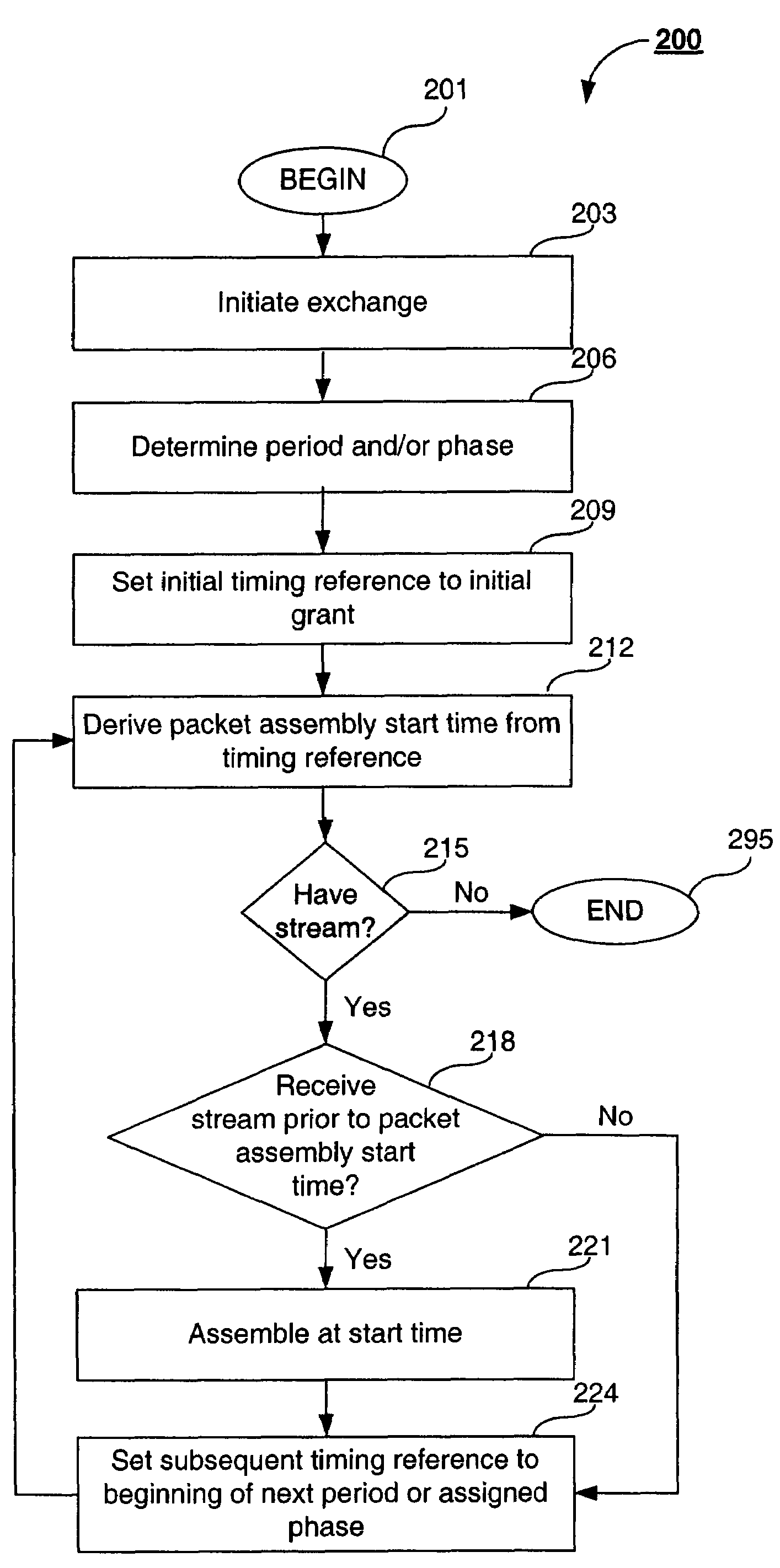
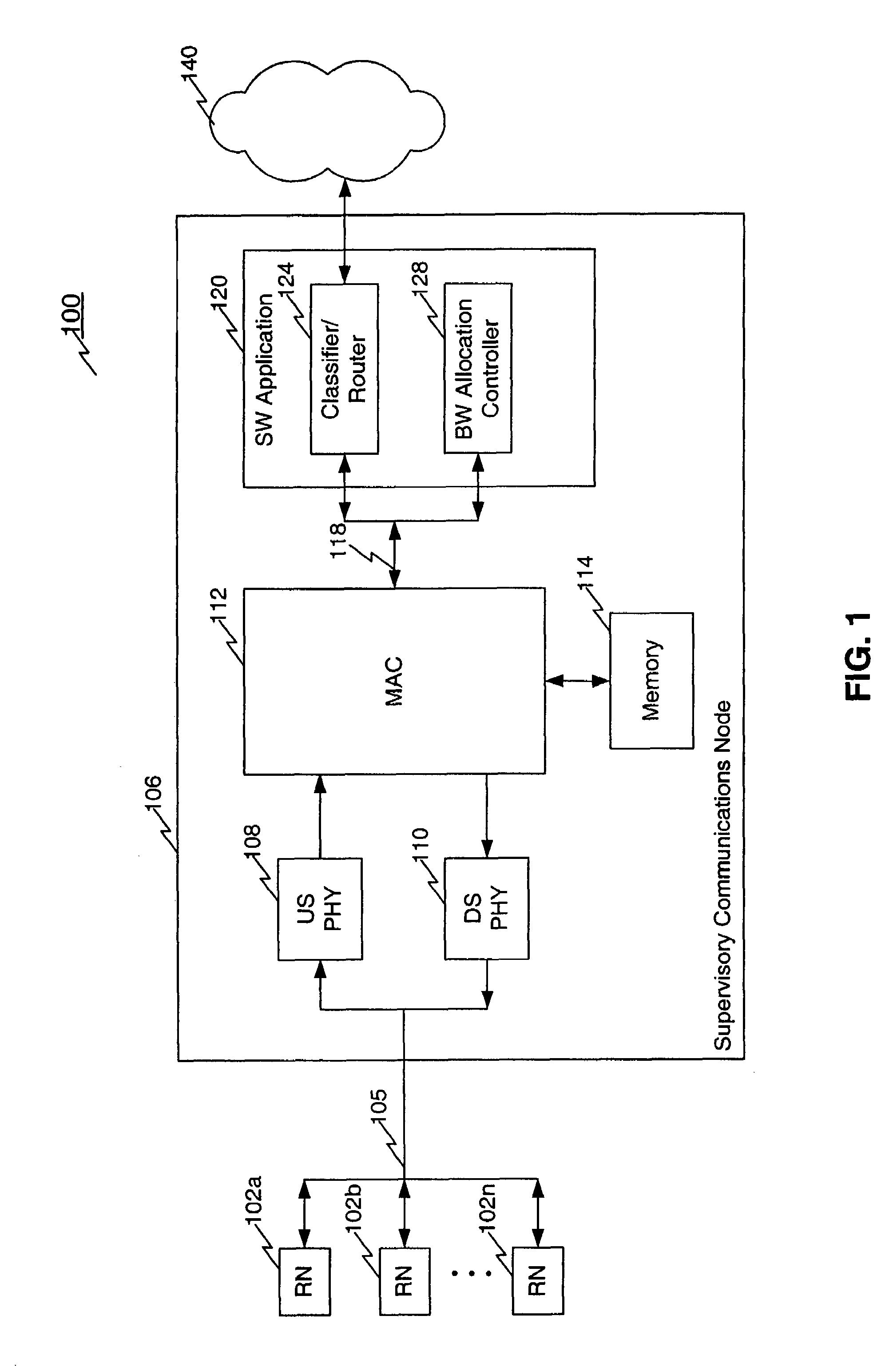
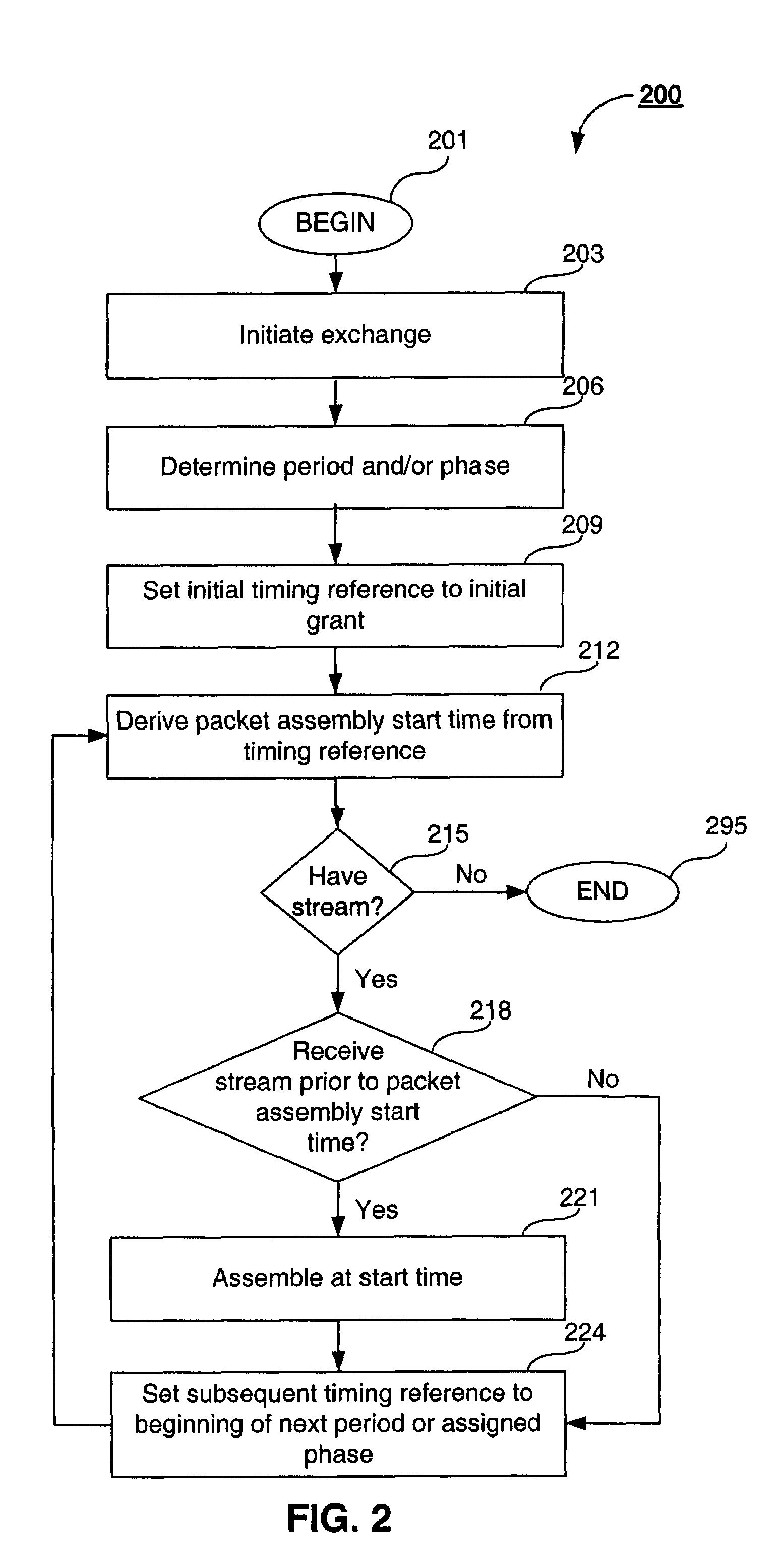
[0030]The method of the present invention convey and maintain synchronization information within a communications network. A supervisory communications node (such as, a cable modem termination system (CMTS) for a headend controller) communicates a synchronization timing reference to a plurality of remote communications nodes (such as, a cable modem). The remote communications nodes use the synchronization timing reference to synchronize their respective packetization and burst operations. Such synchronization ensures that a packet is ready for transmission when a grant arrives, and therefore, improves overall delay performance.

[0031]As such, the present invention includes various methodologies and / or techniques for providing ...


PUM


Abstract

A supervisory communications node monitors and controls communications with a plurality of remote devices throughout a widely distributed network. A method is provided to convey and maintain information used to synchronize the packetization and burst operations within the network. During session setup, jitter constraints indirectly are used to explicitly communicate a synchronization timing reference. The timing reference is set at the beginning of a phase / period boundary used to service the session. In an embodiment, the announcement of the first grant is used as an explicit indication of the synchronization timing reference value. In another embodiment, the synchronization timing reference value is inferred if a remote device receives contiguous voice grants meeting certain conditions. In an embodiment implementing periodic scheduling, the actual arrival of the first grant is used to infer the synchronization timing reference value. In an embodiment, the present invention enables the synchronization timing reference value and / or the periodicity to be modified if network conditions indicate that packetization and burst operations are out-of-synchronization.

Description

CROSS-REFERENCE TO RELATED APPLICATIONS[0001]This application is a continuation of and claims benefit to U.S. patent application Ser. No. 10 / 197,436, filed Jul. 18, 2002 by Sala et al., entitled Method, System and Computer Program Product for Synchronizing Voice Traffic with Minimum Latency, which is incorporated here in its entirety.[0002]The '436 application in turn claims the benefit of U.S. Provisional Application Ser. No. 60 / 327,298, filed Oct. 9, 2001, by Sala et al., entitled “A Synchronization Method to Support Voice Traffic with Minimum Latency,” incorporated herein by reference.[0003]The following United States patent applications have a common assignee and contain some common disclosure:[0004]“Cable Modem with Sample and Packet Synchronization,” U.S. patent application Ser. No. 09 / 501,850, by Rabenko et al., filed Feb. 10, 2000, incorporated herein by reference as though set forth in its entirety;[0005]“Cable Modem with Sample and Packet Synchronization,” U.S. patent appl...

Claims


Application Information

Patent Timeline
Patent Type & Authority Patents(United States)
IPC IPC(8): H04J3/24H04J3/06H04L12/43H04L12/56
CPCH04L12/5695H04L47/15H04L47/2416H04L47/28H04L47/828H04L47/788H04L47/801H04L47/826H04L47/762H04L47/70
Inventor SALA, DOLORSGUMMALLA, AJAY CHANDRA V.RABENKO, TED
Owner AVAGO TECH INT SALES PTE LTD
Learn More