
Fault detection system and method for turbine engine fuel systems

a technology of turbine engine and fuel system, applied in the field of diagnostic systems, can solve the problems of increasing the need for automatic fault detection systems, increasing the complexity of modem aircraft, and large amount of data typically required to fully analyze the performance of turbine engines, and achieve the effect of accurately classifying the performance of the turbine engine fuel system and efficient analysis of data

Inactive Publication Date: 2010-04-06
HONEYWELL INT INC
View PDF17 Cites 34 Cited by
  • Summary
  • Abstract
  • Description
  • Claims
  • Application Information

AI Technical Summary

Benefits of technology

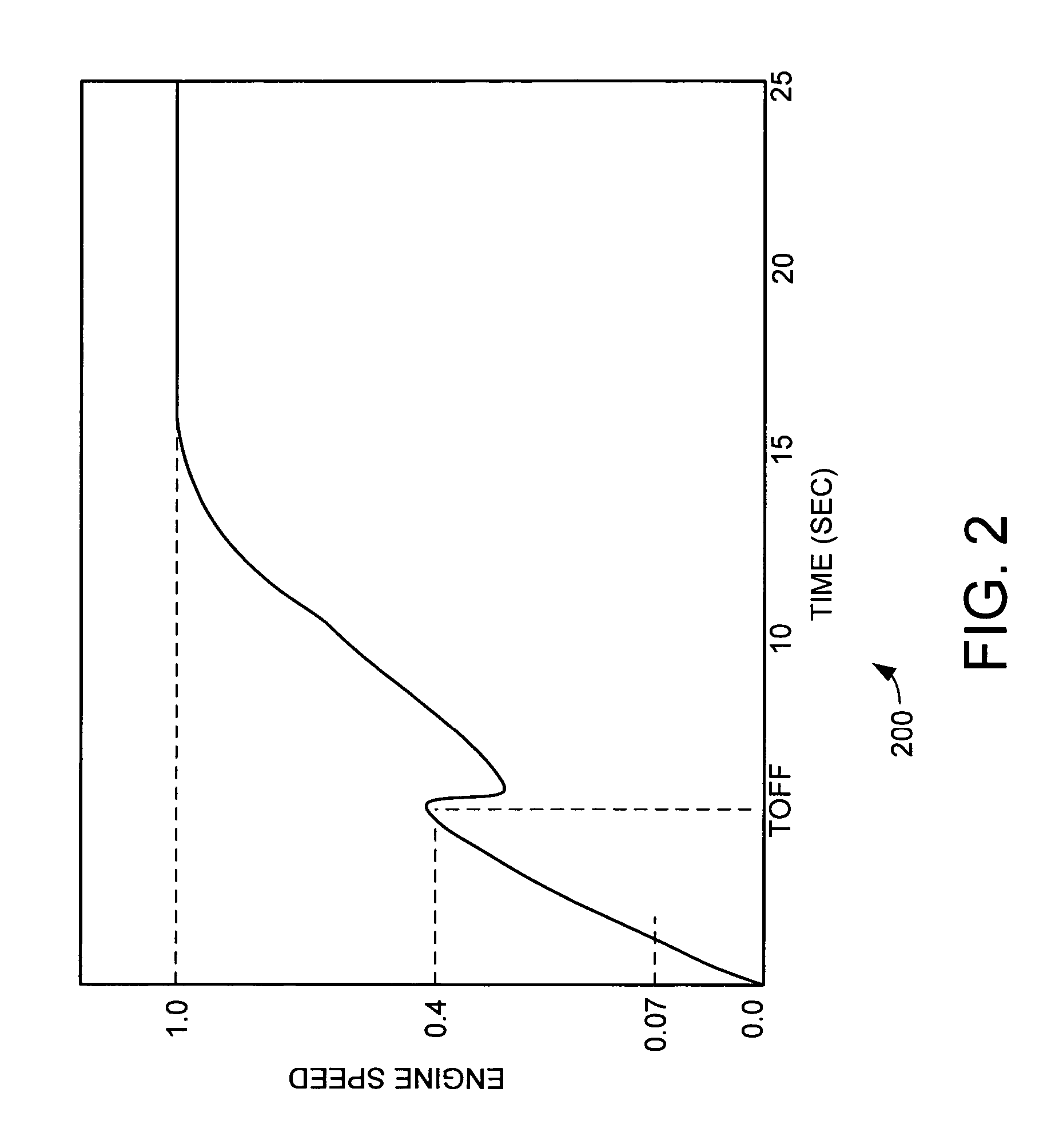
[0006]The fault detection system and method is particularly applicable to faults that occur in the hydro-mechanical assembly (HMA) of the turbine engine. For this application a statistical analysis has been applied to identify a specific subset of sensor data parameters that are highly indicative of HMA anomalies. The fault detection system monitors turbine engine sensor data during engine startup and collects the specified subset of data. This subset of sensor data is passed to the feature extractor. The feature extractor extracts salient features from the set of turbine engine sensor data. This extraction reduces the original subset of turbine sensor data into a substantially reduced set of variables, and the extracted features are passed to the classifier. The reduced set of variables in the extracted salient features allows the classifier to efficiently analyze the data for symptoms of HMA failure and accurately classify the performance of the turbine engine fuel system. Thus, the fault detection system provides improved fault detection for turbine engine fuel systems.

Problems solved by technology

Modem aircraft are increasingly complex.
The complexities of these aircraft have led to an increasing need for automated fault detection systems.
One problem with fault detection in turbine engines has been the large amounts of data typically required to fully analyze the performance of the turbine engine.
In many cases such large amounts of data are not available from the engine or cannot be reasonably stored and passed to the fault detection system due to limitations in hardware.
For example, smaller turbine engines may be limited data sensors and recording ability.
This has limited the ability to perform effective fault detection in some applications.
The proper delivery of fuel is critical to the operation of a turbine engine and as such a failure in the fuel system will commonly lead to failure of the turbine engine.
Unfortunately, previous methods of fault detection in fuel systems of turbine engines have been limited in effectiveness.

Method used


Image

  • Fault detection system and method for turbine engine fuel systems
  • Fault detection system and method for turbine engine fuel systems
  • Fault detection system and method for turbine engine fuel systems

Examples


Embodiment Construction

[0016]The present invention provides a fault detection system and method that provides improved fault detection. The fault detection system provides the ability to detect symptoms of fault in the fuel system of a turbine engine.

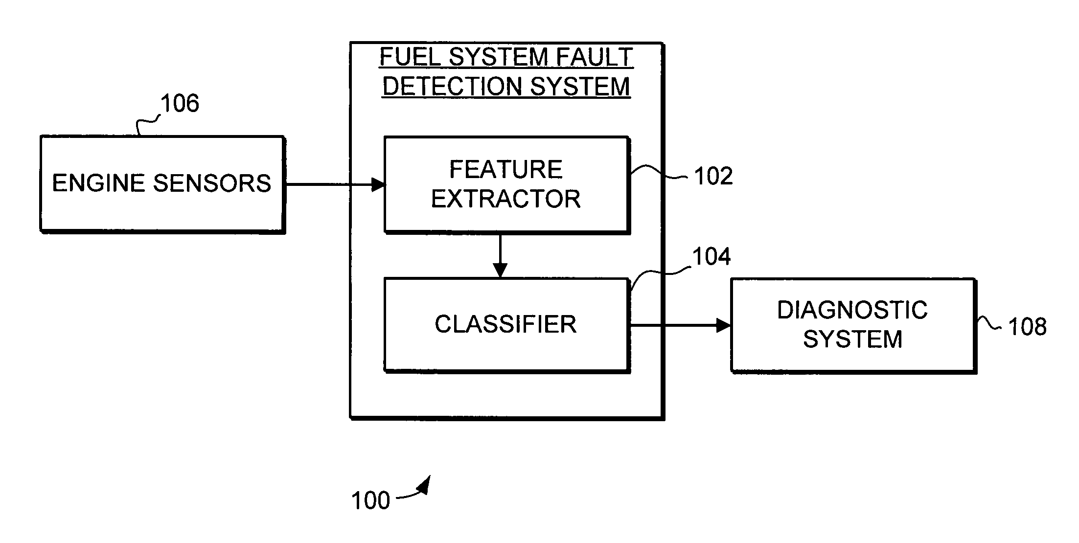
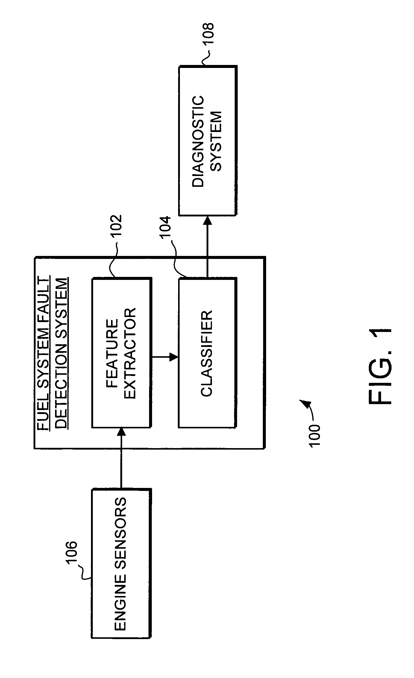
[0017]Turning now to FIG. 1, a fault detection system 100 for turbine engine fuel systems is illustrated. The fault detection system 100 includes a feature extractor 102 and a classifier 104. Turbine sensor data that is indicative of the anomalies of interest is identified and collected. This indicative set of turbine engine sensor data from the engine sensors 106 is passed to the feature extractor 102. The feature extractor 102 extracts salient features from the turbine engine sensor data. This extraction reduces the original turbine sensor data into a substantially reduced set of variables that can be used to efficiently detect problems in the fuel system. The extracted salient features are then passed to the classifier 104. The reduced set of variables in ...


PUM


Abstract

A system and method is provided that facilitates improved fault detection. The fault detection system provides the ability to detect symptoms of fault in the fuel system of a turbine engine. The fault detection system captures selected data from the turbine engines that is used to characterize the performance of the fuel system. The fault detection system includes a feature extractor that extracts salient features from the selected sensor data. The extracted salient features are passed to a classifier that analyzes the extracted salient features to determine if a fault is occurring or has occurred in the turbine engine fuel system. Detected faults can then be passed to a diagnostic system where they can be passed as appropriate to maintenance personnel.

Description

FIELD OF THE INVENTION[0001]This invention generally relates to diagnostic systems, and more specifically relates to fault detection in turbine engines.BACKGROUND OF THE INVENTION[0002]Modem aircraft are increasingly complex. The complexities of these aircraft have led to an increasing need for automated fault detection systems. These fault detection systems are designed to monitor the various systems of the aircraft in an effect to detect potential faults. These systems are designed to detect these potential faults such that the potential faults can be addressed before the potential faults lead to serious system failure and possible in-flight shutdowns, take-off aborts, and delays or cancellations.[0003]Engines are, of course, a particularly critical part of the aircraft. As such fault detection for aircraft engines are an important part of an aircrafts fault detection system. One problem with fault detection in turbine engines has been the large amounts of data typically required ...

Claims


Application Information

Patent Timeline
Patent Type & Authority Patents(United States)
IPC IPC(8): G06F19/00F02C7/26
CPCF01D21/14F02C7/22F02C7/264F02C9/28F02C9/46F05D2270/707Y02T50/677F05D2270/44F05D2270/708F05D2270/709F05D2270/304F05D2270/0831Y02T50/60
Inventor KIM, KYUSUNGULUYOL, ONDERBALL, CHARLES M.
Owner HONEYWELL INT INC
Learn More