Operating table

a technology of operating table and pivoting mechanism, which is applied in the field of operating table, can solve the problems of severe restrictions on at least one pivoting movement, greatly restricted lowering of the operating table to a low level,

Active Publication Date: 2010-04-13
MAQUET GMBH
View PDF108 Cites 20 Cited by
  • Summary
  • Abstract
  • Description
  • Claims
  • Application Information

AI Technical Summary

Benefits of technology

[0005]The object on which the invention is based is to specify an operating table of the type mentioned in the introduction, which allows greater latitude in the adjustment of the bed about its axis of inclination and / or axis of tilt and in the vertical direction.
[0007]Since the saddle coupled to the patient bed slides externally on the curved guide track, there is no need for the pivot axis to be mounted so as to pass through the column head. This gives rise, within the column head, to free space which is available for height adjustment and allows a greater lift of the height drive. In particular, this type of construction also makes it possible for the column head together with the patient bed to be lowered to a greater extent. Since, at least in the case of a convexly curved guide track, the saddle can be moved as far as the end of the respective guide track, the angle of inclination of the patient bed can also be made very large correspondingly to the curvature of the guide track, without the patient bed butting against the column head.
[0009]Preferably, the saddle drive has at least one push and / or pull element which is flexible at least in one direction and which is guided displaceably along the guide track and is connected, on the one hand, to the saddle and, on the other hand, to an actuator. A saddle drive can thereby be provided which, on the one hand, can exert a high force and, on the other hand, occupies only a small amount of space. Preferably, the actuator is a linear drive, for example a pressure-medium-actuated cylinder. A particularly space-saving and yet functionally reliable design of the saddle drive can be achieved in that the push and / or pull element is a rigid-back chain which can bend in only one direction. Such a chain can be connected directly to the piston of the pressure-medium-actuated cylinder and forms as it were a rigid piston rod which is nevertheless bendable, that is to say deflectable, on one side. A linear drive can thereby be provided, the stroke of which corresponds approximately to its overall length and in which no additional space is required for the extension of the piston rod.
[0012]To pivot the head frame about its pivot axis, it is proposed that the pivoting drive comprise two pressure-medium-actuated pivoting cylinders which are arranged within the column and, on the one hand, are supported on the column head and, on the other hand, engage on the head frame on both sides of the pivot axis. In this way, the necessary force for pivoting the patient bed can be applied conveniently. In another possibility, the pivoting drive comprises at least one worm wheel connected fixed in terms of rotation to the head frame and arranged coaxially with respect to the pivot axis and a worm which can be driven by means of a motor and is in engagement with the worm wheel.
[0015]In the preferred embodiment in which the axis of curvature of the guide track is identical to the axis of inclination, the pivoting of the patient bed about its pivot axis affords a further advantage, in combination with the displacement of the saddle on the guide track. When the saddle is displaced from one end of the guide track towards to the other end of the guide track, the patient bed can always be kept in a horizontal position by the latter simultaneously being pivoted in the opposite direction. The final effect is a horizontal displacement of the patient bed with respect to the supporting column, without a specific guide or a specific drive being required for this purpose. Moreover, in this case, in the position of the saddle at the end of the guide track, an additional lowering of the patient bed with respect to the middle position of the saddle, that is to say the highest point of the guide track, also occurs, without a height adjustment of the column head being required for this purpose. When the saddle is displaced towards one end and the patient bed pivots in the same direction, the pivot angles are added up to form a very large achievable angle of inclination.

Problems solved by technology

If the pivot axes are arranged above the lift guide in order to achieve sufficient freedom for the pivoting movements in the tilt and inclination directions, a lowering of the operating table to a low level is greatly restricted.
If, on the other hand, the pivot axes are arranged such that they pass through the lift guide, this results in severe restrictions of at least one pivoting movement.

Method used


Image

  • Operating table
  • Operating table
  • Operating table

Examples


Embodiment Construction

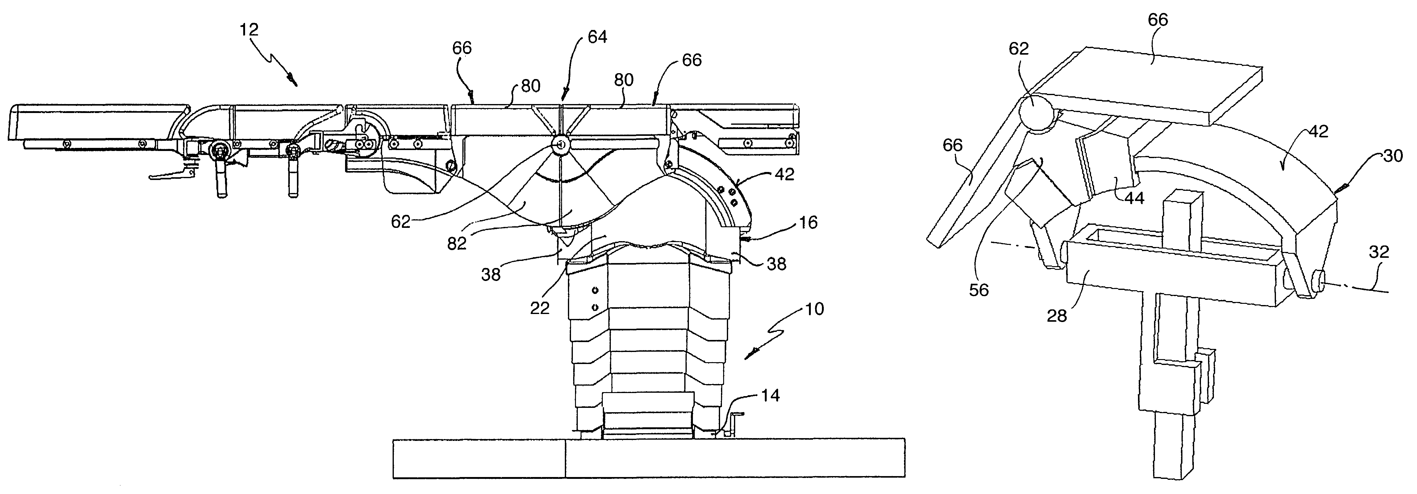
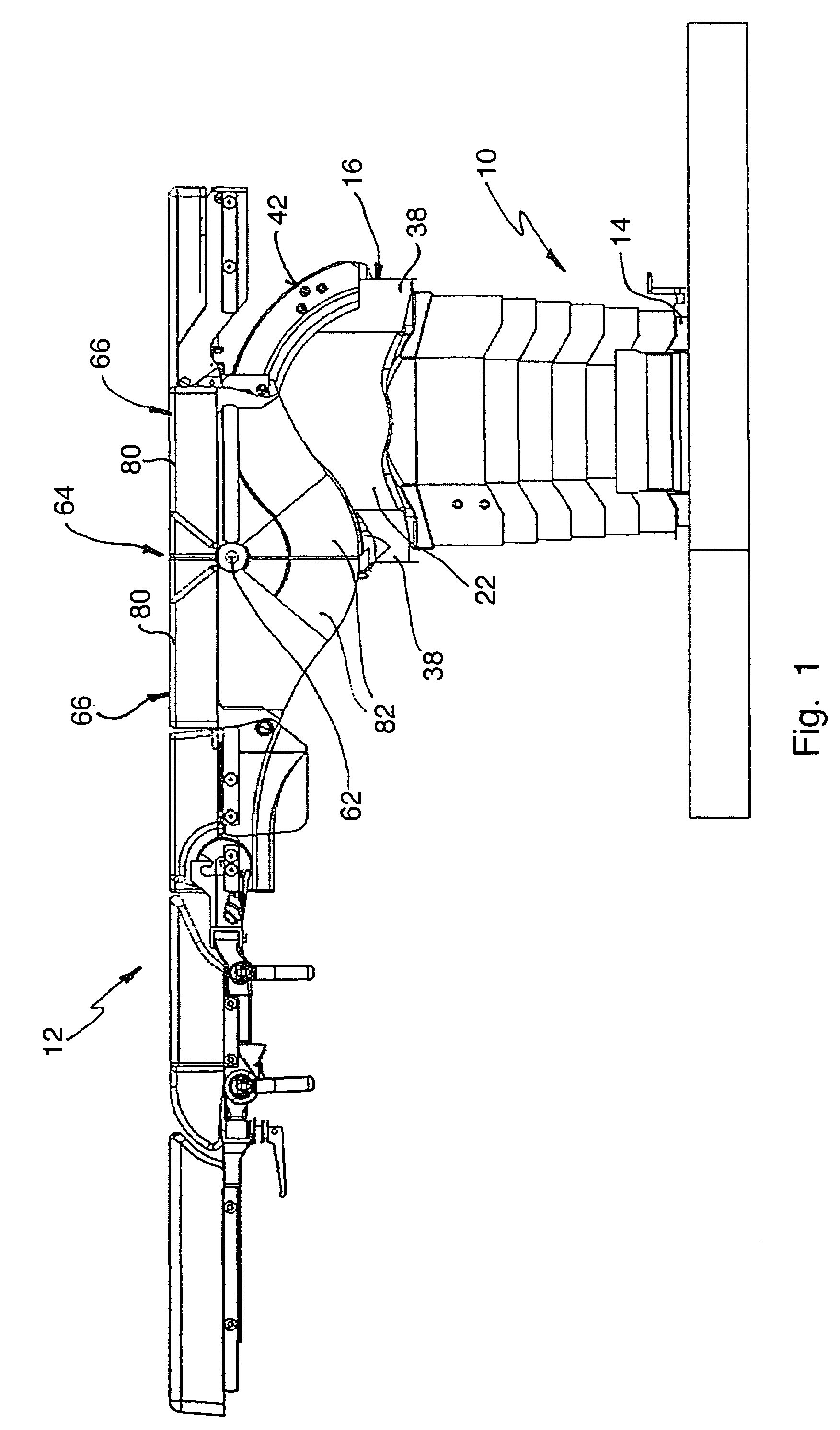
[0028]The operating table illustrated in FIG. 1 comprises an operating table column, designated in general by 10, and a patient bed 12 arranged on the latter. The table column or supporting column has a column foot 14 and a column head 16. Of the column portion lying between the column foot and column head, FIG. 1 shows only a cladding 18 which covers the carrying elements and height adjustment device and which comprises a multiplicity of ring-like elements which are displaceable telescopically in relation to one another during the height adjustment of the column, that is to say during the lowering and raising of the column head 16.

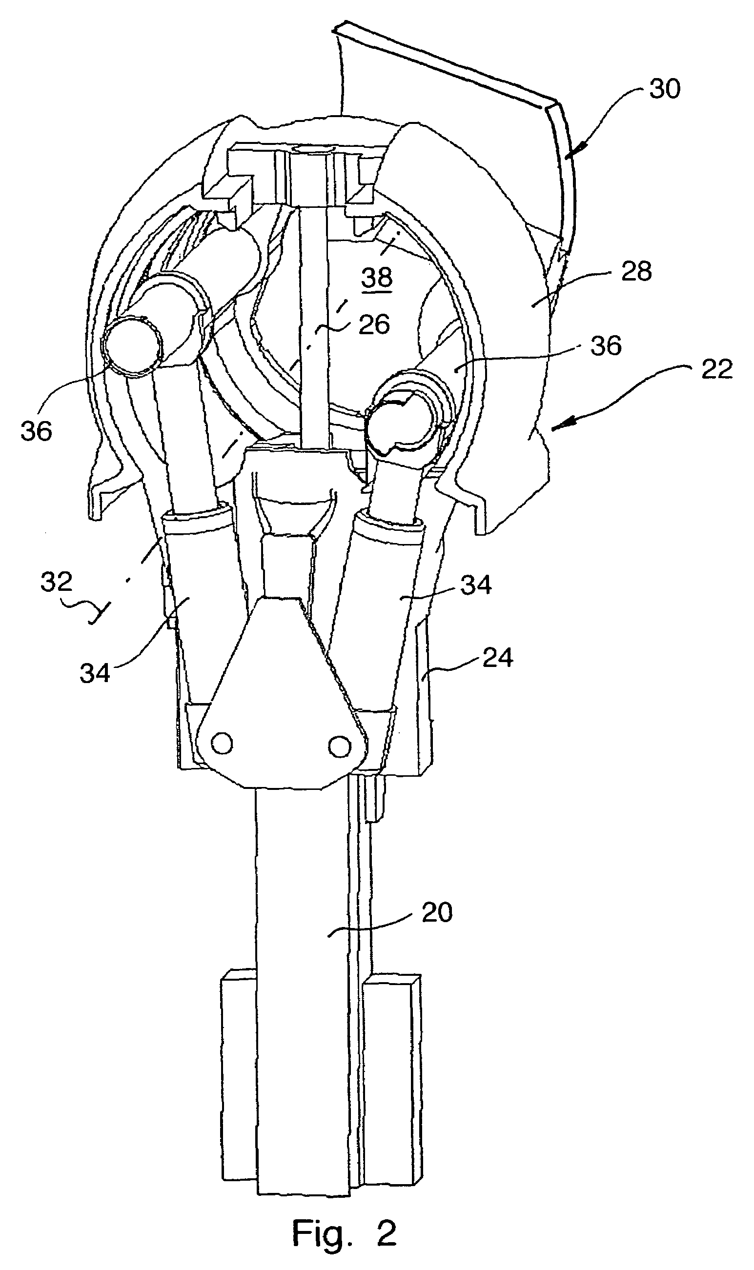
[0029]FIG. 2 shows part of the internal construction of the supporting column 10. A head part 22 is guided vertically displaceably on a vertical guide 20 by means of a guide portion 24. The displacement of the head part 22 takes place by means of a pressure-medium-actuated cylinder, of which FIG. 2 shows only the piston rod 26 which engages on the inner u...


PUM


Abstract

In an operating table comprising a table column (10) with a column foot (14) and with a column head (16) and also a patient bed (12) which is connectable to the column head (16) and which is pivotable in relation to the table column (10) about at least one axis parallel to the bed plane, the column head (16) has provided on it a guide track (42) which is curved continuously about an axis of curvature and on which a saddle coupleable to the bed (12) is mounted such that it can be adjusted along the guide track (42) by means of a saddle drive.

Description

CROSS REFERENCE TO RELATED APPLICATIONS[0001]Applicant hereby claims foreign priority benefits under U.S.C. § 119 from German Patent Application No. 10 2005 054 222.0 filed on Nov. 14, 2005, the contents of which are incorporated by reference herein.FIELD OF THE INVENTION[0002]The invention relates to an operating table comprising a table column with a column foot and with a column head and also a patient bed which is connectable to the column head and is pivotable in relation to the table column about at least one axis parallel to the bed plane.BACKGROUND OF THE INVENTION[0003]Operating tables of the abovementioned type are, as a rule, mounted on the column head pivotably both about an axis (axis of inclination) directed transversely to the longitudinal direction of the patient bed and about an axis (axis of tilt) directed parallel to the longitudinal direction of the patient bed.[0004]The bed must be at a relatively great distance from its pivot axes, so that it can execute a suff...

Claims


Application Information

Patent Timeline
Patent Type & Authority Patents(United States)
IPC IPC(8): A61G7/005A61G7/008A61G7/015A61G7/018
CPCA61G13/04A61G13/08A61G13/06A61G13/02A61G13/00
Inventor KOCH, GUIDOKOBU.BETA., MATTHIASKOTTMANN, HEIKOOLSZEWSKI, JAN DONAT
Owner MAQUET GMBH
Why Eureka
Try Eureka