Dispenser having a pivoting actuator assembly

a technology of actuator assembly and dispenser, which is applied in the direction of liquid transferring device, valve operating means/releasing device, instruments, etc., can solve the problems of unfavorable dispensing discontinuities, increased requirements, and friction and seal wear, so as to reduce or eliminate stagnation points, reduce or eliminate the formation of char and other material buildup

Inactive Publication Date: 2010-04-13
NORDSON CORP
View PDF28 Cites 36 Cited by
  • Summary
  • Abstract
  • Description
  • Claims
  • Application Information

AI Technical Summary

Benefits of technology

[0009]The actuator assembly includes a pivoting lever arm having a first end coupled with the piston and a second end coupled with the needle. In one aspect of the invention, the second end of the pivoting lever arm couples with the needle at a point located between the inlet and outlet. Coupling the end of the pivoting lever arm with the second moveable member, such as the needle, between the inlet and outlet advantageously reduces or eliminates stagnation points and consequently reduces or eliminates the formation of char and other material buildup within the hydraulic section. The actuator assembly further includes a flexible seal coupled with the pivoting lever arm and adapted to be positioned between the actuating section and the hydraulic section to prevent liquid from leaking into the actuating section. The seal can be a non-diaphragm seal wherein the periphery of the seal is unrestrained and is capable of flexing to accommodate the movement of the pivoting lever arm while retaining a fluid-tight seal. The seal may be further adapted to withstand large hydraulic operating pressures, such as from approximately 80 psi to at least 1,500 psi and other pressure ranges. A bushing support may be provided that couples with the pivoting lever arm and supports the seal. The bushing support is positioned radially inward of the seal's periphery. Furthermore, the actuator assembly may also include a pivoting member, such as a pivoting pin, coupled with the pivoting lever arm and adapted to define a fixed pivot point around which the pivoting lever arm pivots.

Problems solved by technology

These dynamic seals may press tightly against the valve stem and cause friction and seal wear.
The higher friction may place greater demands on the requirements for pressurized air to move the valve stem.
On the other hand, selecting a looser dynamic seal could result in inadequate sealing, thus allowing the liquid to bind the piston and pressurized air to enter into the liquid passage, causing undesired dispensing discontinuities.
Even with reduced friction, the dynamic seal will wear over time and lose its ability to seal properly.

Method used


Image

  • Dispenser having a pivoting actuator assembly
  • Dispenser having a pivoting actuator assembly
  • Dispenser having a pivoting actuator assembly

Examples


Embodiment Construction

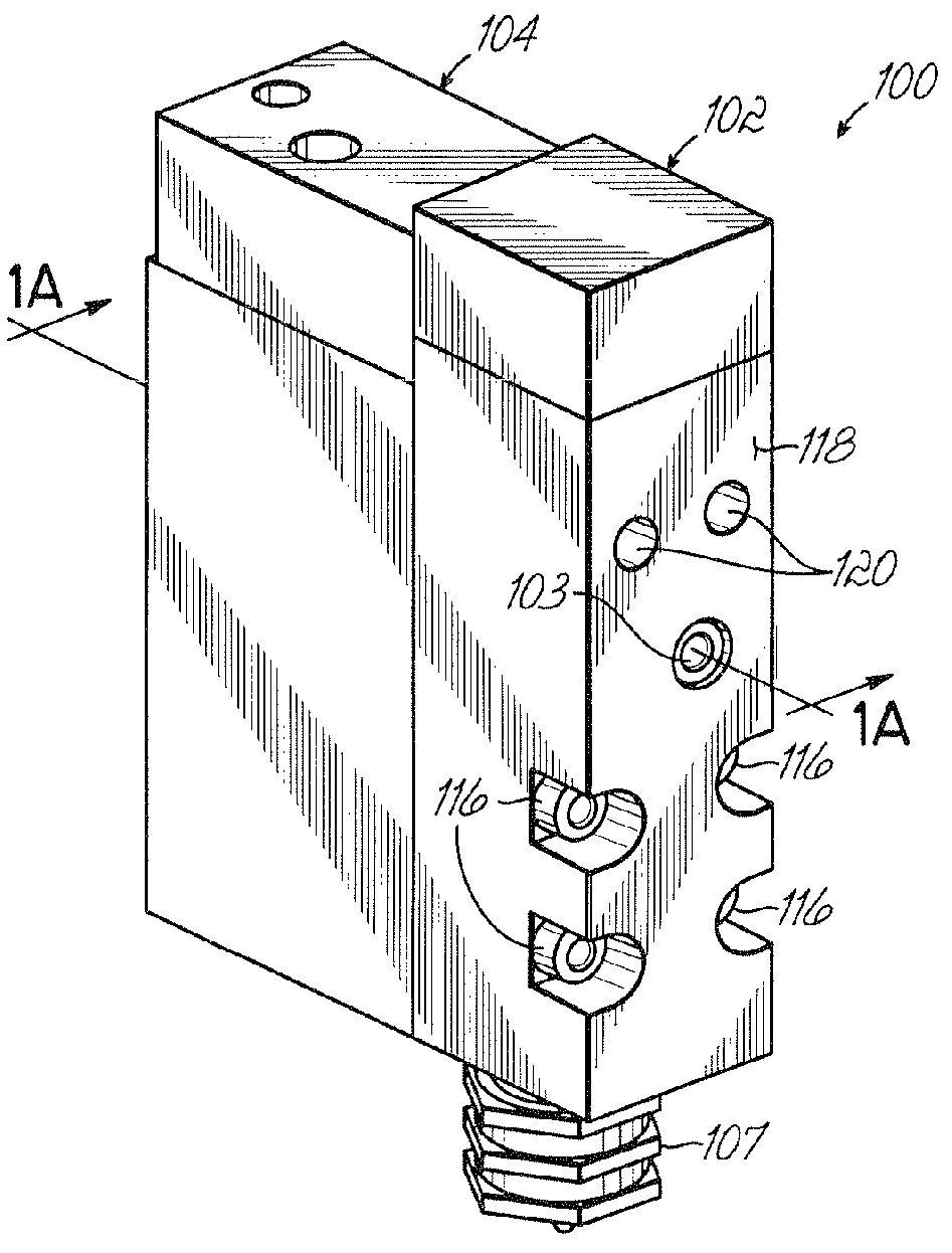
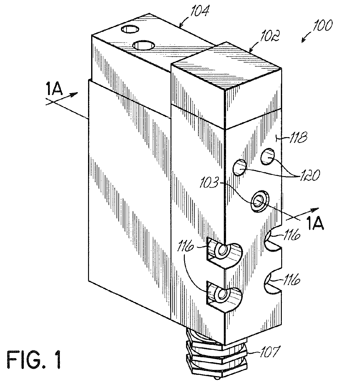
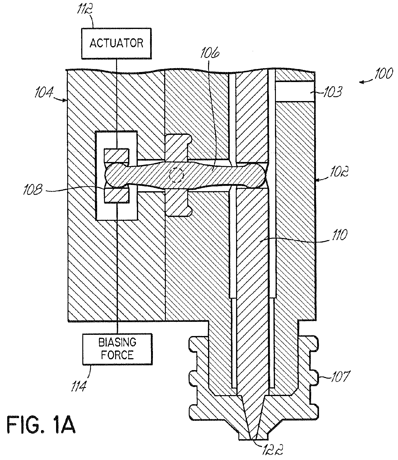
[0029]FIG. 1 is a schematic depiction of an exemplary dispenser in accordance with the invention. Unlike previous dispensers, the dispenser of the invention includes a hydraulic section 102 and an actuating section 104 arranged in a side-by-side manner instead of in a vertical manner. As the hydraulic section 102 is often coupled with a heated manifold or other heater block, the present side-by-side arrangement allows the actuating section 104 to be thermally isolated from such a heater block. As a result, O-rings and other seals within the actuating section 104 should not be exposed to the same high temperatures as experienced in conventional dispensers. Additionally, other electrical components, such as, for example, solenoids, will not be exposed to high temperatures as well. This permits closer coupling of the solenoid with the actuating section, which improves response time. Overall, the side-by-side arrangement will provide increased reliability and performance over the conven...


PUM


Abstract

A dispenser includes an actuating section having a first moveable member and a hydraulic section coupled with the actuating section and having a second moveable member. The hydraulic section is adapted to dispense a liquid from an outlet therein and the actuating section is adapted to control dispensing of the liquid. An actuator assembly operatively couples the first moveable member with the second moveable such that the first moveable member is operative to move the second moveable member between open and closed positions for respectively starting and stopping flow of liquid from the outlet. The actuator assembly may include a pivoting lever arm having a first end operatively coupled with the first moveable member, a second end operatively coupled with the second moveable member and defining a fixed pivot point therebetween.

Description

RELATED APPLICATION[0001]This application claims the benefit of U.S. Provisional Application No. 60 / 565,161 filed on Apr. 23, 2004, the entire disclosure of which is hereby incorporated by reference herein. This application is also a continuation-in-part of U.S. application Ser. No. 10 / 975,227, filed on Oct. 28, 2004, the entire disclosure of which is hereby incorporated by reference herein.FIELD OF THE INVENTION[0002]This invention generally relates to liquid dispensing devices used for a variety of purposes, but particularly useful for viscous liquids such as hot melt adhesives, sealing compounds, paints, etc. Such devices are referred to as fluid control valves or dispensing guns or modules.BACKGROUND OF THE INVENTION[0003]A typical dispensing device for supplying liquid, such as hot melt adhesive, generally includes a body having a valve stem that opens and closes a dispensing orifice. The valve stem is usually actuated in at least one direction by pressurized air to dispense di...

Claims


Application Information

Patent Timeline
Patent Type & Authority Patents(United States)
IPC IPC(8): B67D7/80F16K11/052F16K31/02B05B1/30F16K31/163B05C5/00B05C5/02B05C11/10B67D7/06
CPCB05C5/001B05C5/0237B05C11/1042Y10T137/86847Y10T137/87812
Inventor CHASTINE, CHRISTOPHER RRINEY, JOHN MSAIDMAN, LAURENCE B
Owner NORDSON CORP
Why Eureka
Try Eureka