Filtering device

a filter device and filtering technology, applied in gravity filters, water treatment locations, loose filtering material filters, etc., can solve the problems of reducing the speed or stopping of the filtering process, closing the effective cross-section, and insufficient manufacturability of the net construction, so as to improve the reliability and operating characteristics of the device.

Active Publication Date: 2010-04-13
OBSHCHESTVO S OGRANICHENNOJ OTVETSTVENNOSTJU OOO AKVAFOR OOO AKVAFOR
View PDF4 Cites 19 Cited by
  • Summary
  • Abstract
  • Description
  • Claims
  • Application Information

AI Technical Summary

Benefits of technology

[0010]The main purpose of claimed invention is to improve the reliability and operating characteristics of the device.
[0011]The purpose is solved by a filtering device consisting of a body filled with a particulate filtering material and provided with at least one outlet in the base of it, a lid provided with water inlets and air outlets and at least one fixing means disposed between the body and the lid for preventing the particulate filtering material from escaping from the body through the water inlets and the air outlets, wherein the fixing means is formed from a flexible polymeric material and is provided with at least one slit formed therein thereby defining a valve for providing increasing water filtering efficiency. The shape of the valve is expressed by: to 1≦Lp / Lo≦2, where: Lp—the length along the perimeter; Lo—the length of the slit. The width of the slit increases to a width that is at least twice the width of the slit in the closed position during the time when liquid or gas is flowing through it. Furthermore, the width of the slit in the closed position is less than a size of the particulate filtering material and is expressed by the following relationship: 0.1Lo≦d≦3Lo, where: d—the width of the valve; Lo—the length of the valve.

Problems solved by technology

This construction of the net is insufficient manufacturable.
Use of a fixation unit made in form of a net, a membrane or a laying in said filtering devices frequently results in reducing speed or stop the filtering process because of an air bubble, which appears under the fixation means which results in closing its effective cross-section.

Method used


Image

  • Filtering device
  • Filtering device
  • Filtering device

Examples


Embodiment Construction

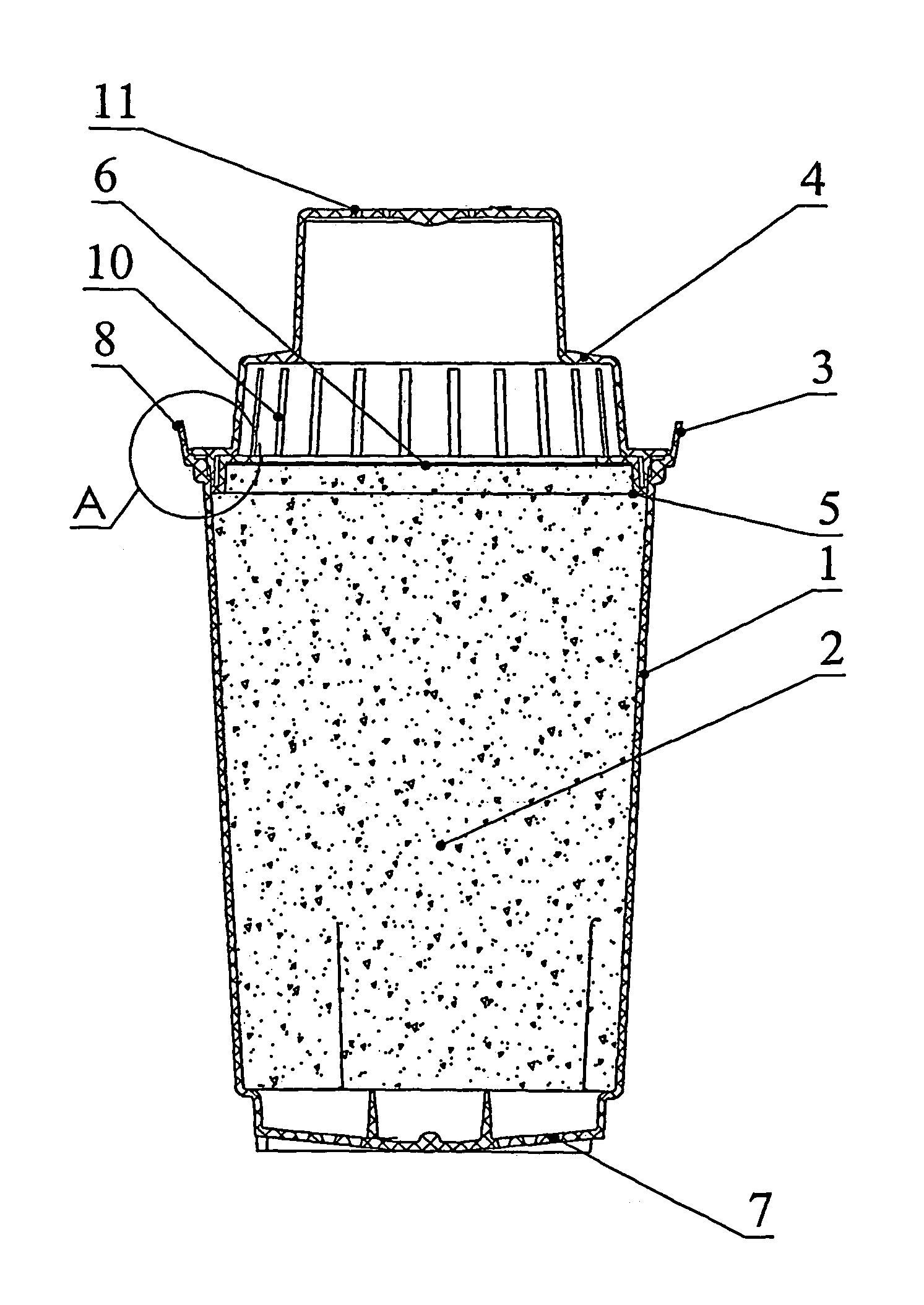
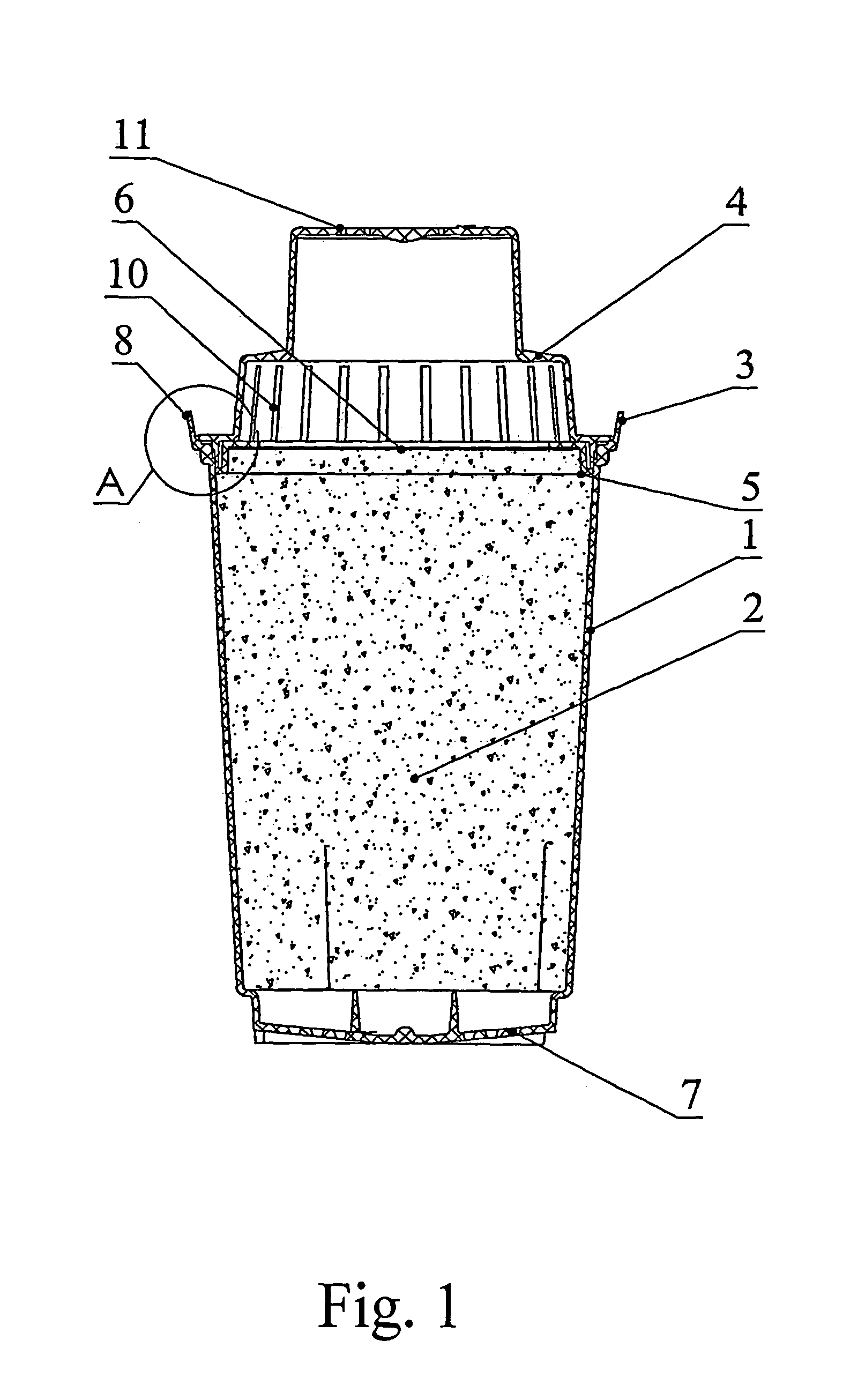
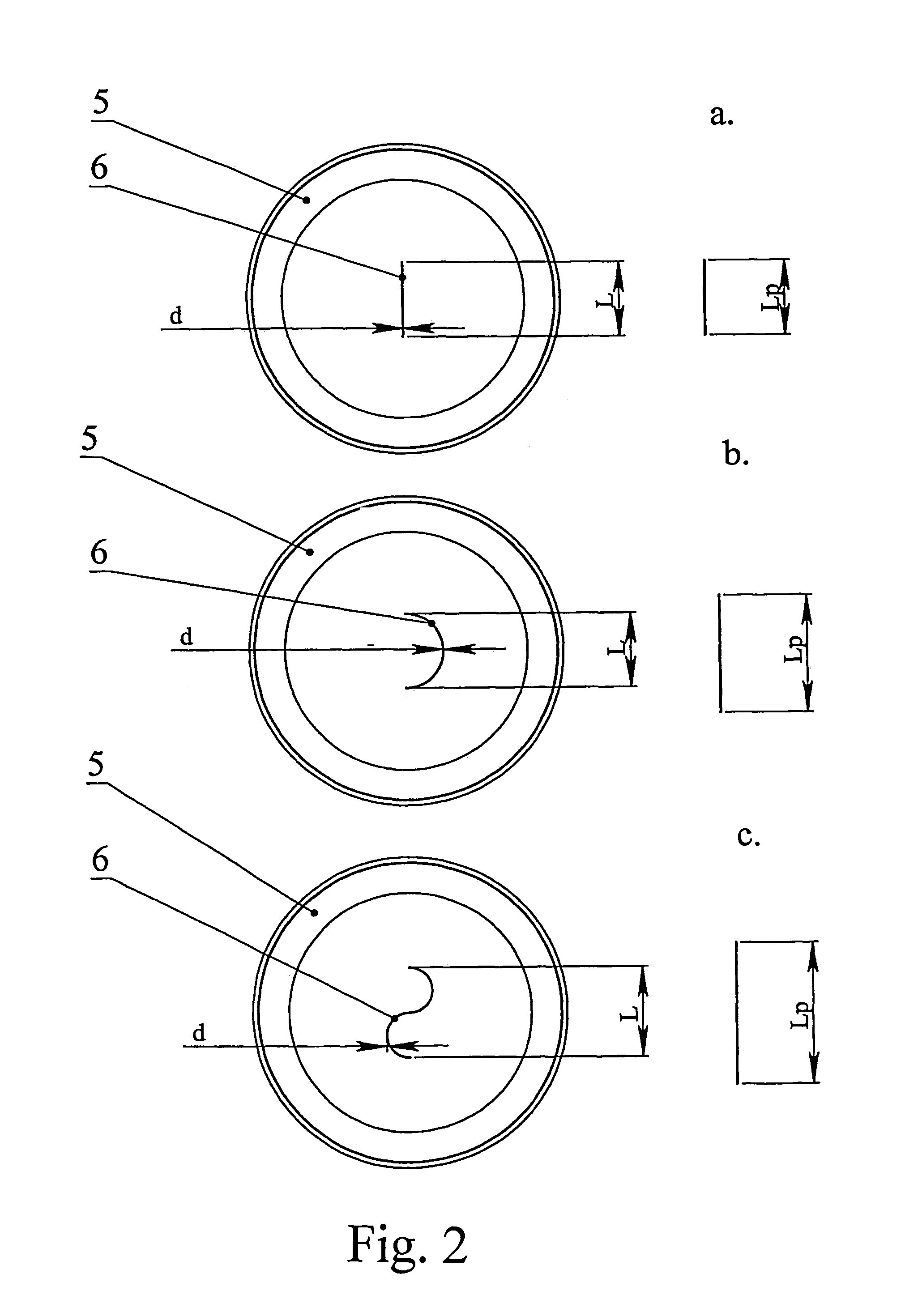
[0022]The filtering device (FIG. 1) consist of a body 1 filled with a filtering material 2 and a cuff 3, a lid 4 and a fixing means 5 with valve 6 of prescribed form, width and length (FIG. 1, 2). The base of the body is designed with cleaned water outlets 7. The body 1 is provided with the cone shape cuff 3, which external surface comprises at least one collar 8 for increasing the reliability of fixing and sealing of the filtering device on the tank for the cleaning water (FIG. 1, 3). The body cuff provides a possibility to increase the construction reliability of the filtering device itself, i.e. to keep sealing properly for a long time owing to ferrule deformation is not happen and, correspondingly, the possibility of falling of uncleaned liquid into the tank for the cleaned liquid is excluded. Furthermore, such construction allows to produce a device of bigger size since the strength characteristics and flexibility of the cuff it saves, and this promotes improving of the operati...


PUM

PropertyMeasurementUnit
widthaaaaaaaaaa
sizeaaaaaaaaaa
sizeaaaaaaaaaa

Abstract

The invention relates to a filtering device for liquid filters, mainly for potable water jug-type filters. The filtering device consists of a body filled with a filtering material and is provided with at least one outlet in the base of thereof, a lid having a water inlet and an air outlet, and at least one fixing means disposed between the body and the lid, wherein the fixing means is provided with at least one valve. The technical result achieved by use of declared the present is improving reliability and operating characteristics of the device.

Description

FIELD OF THE INVENTION[0001]The invention relates to a filtering device for use in liquid filters, mainly for potable water jug-type filters.PRIOR ART[0002]The most known filtering devices (modules) consist of a body filled with a filtering material and a lid. The lid provided with a liquid inlets and air outlets. The bottom part of the body designed with the one or several filtered liquid outlets. Filtering module is inserted into a reservoir for a liquid. The liquid flows through lid holes and downwardly through filtering material. Cleaned liquid gets out through a hole (or holes) situated in the bottom part of the body to receiving tank (reservoir for cleaned water).[0003]To avert filtering material, mainly an activated carbon, get into the water or pour out from a filtering device the material is located between two layings, sheets or nets. U.S. Pat. No. 4,283,283 (publication date: Aug. 11, 1981) discloses a water filter which consist of a tank for a water to be cleaned in a bo...

Claims


Application Information

Patent Timeline
Patent Type & Authority Patents(United States)
IPC IPC(8): B01D24/06C02F1/00B01D24/10C02F1/18
CPCC02F1/003C02F2307/04B01D24/10
Inventor VINOGRADOVA, MARINA ALEKSEEVNAGORYUNOV, VALERY VICTOROVICHKUZMIN, ALEXEI LEONIDOVICHPIMENOV, ALEXANDER VSEVOLODOVICHSHMIDT, JOSEPH LVOVICH
Owner OBSHCHESTVO S OGRANICHENNOJ OTVETSTVENNOSTJU OOO AKVAFOR OOO AKVAFOR
Why Eureka
Try Eureka