
Primitive oriented assembly for parallel vertex/geometry processing

a parallel vertex and geometry technology, applied in the field of graphic technology for generating vertex and primitive information in the graphics system, can solve the problems of limited scalability, practical limits on the size of a single v-cache, and problems with scalability

Active Publication Date: 2010-04-20
NVIDIA CORP
View PDF5 Cites 21 Cited by
  • Summary
  • Abstract
  • Description
  • Claims
  • Application Information

AI Technical Summary

Benefits of technology

The patent describes a method for performing graphics processing using parallel processing units that do not share vertex information. The method includes generating independent batches of work for each processing unit, with each batch containing a complete list of vertices for a set of primatives. This allows for efficient processing of graphics data across multiple units. The technical effect of this method is improved performance and efficiency in generating and processing graphics data.

Problems solved by technology

However, one drawback of a rotating V-cache architecture is that it limits scalability.
However, there are practical limits on the size of a single V-cache.
However, coordination of different units with a shared V-cache resource creates problems with scalability.

Method used


Image

  • Primitive oriented assembly for parallel vertex/geometry processing
  • Primitive oriented assembly for parallel vertex/geometry processing
  • Primitive oriented assembly for parallel vertex/geometry processing

Examples


Embodiment Construction

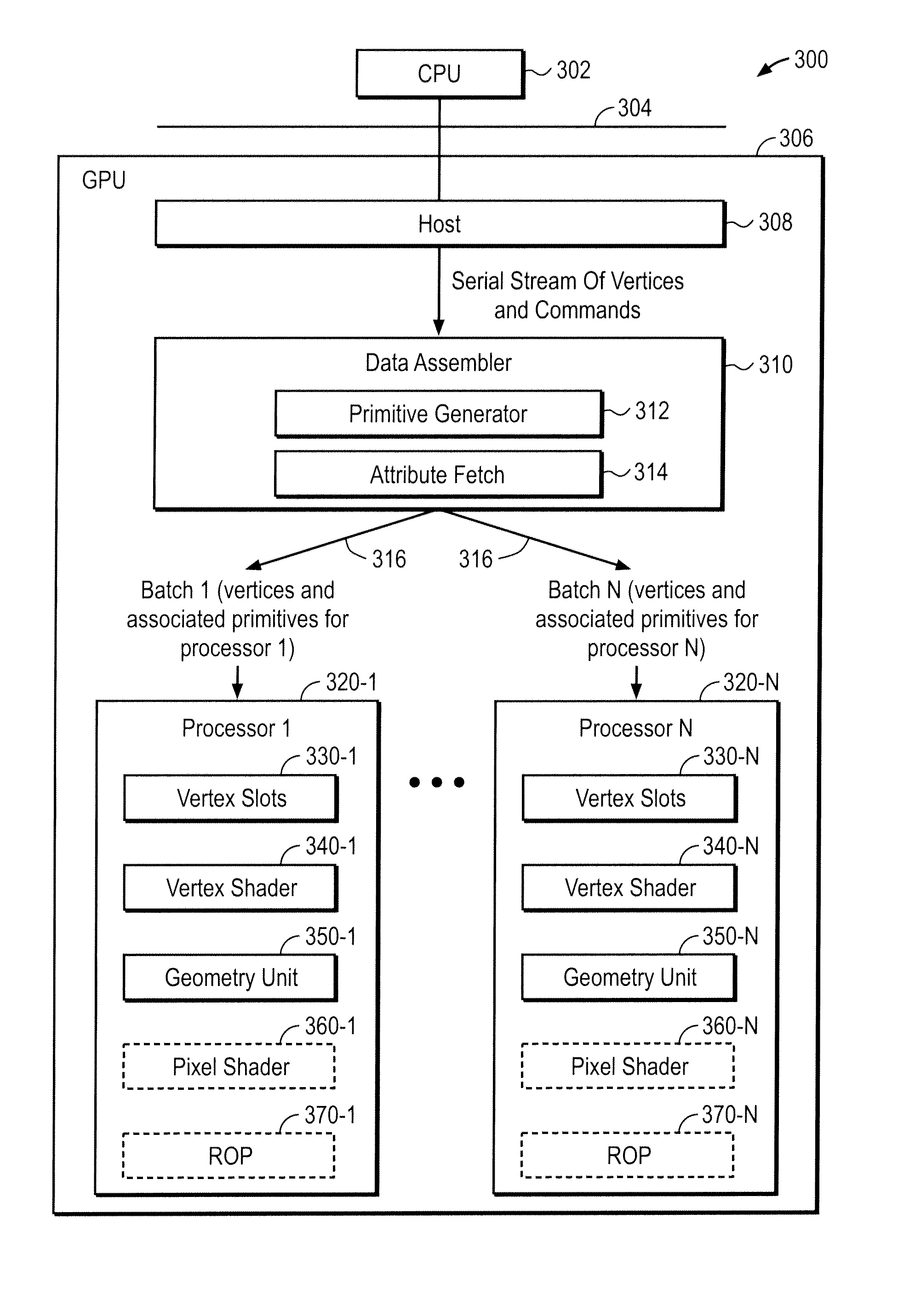
[0015]FIG. 3 illustrates a graphics system 300 in accordance with one embodiment of the present invention. A central processing unit (CPU) 302 is coupled to a graphics processing unit (GPU) 306 by an interface 304 such as a high-speed bus or bridge. In a graphics system, CPU 302 generates commands for the GPU 306 to render pixels for displaying graphical images. A host 308 within GPU 306 acts as an interface with CPU 302 and performs, for example, any necessary translations of abstract graphics commands into a format required by graphics hardware. Host 308 may, for example, receive conventional graphics API calls from CPU 302, such as graphics API calls in accordance with conventional graphics languages for pipelined graphics architectures such as the OpenGL® API.

[0016]A data assembler unit 310 receives a serial stream of vertices and commands from host 308. As an illustrative example, the serial stream may include a “to do” list for a set of vertices and a command indicating operat...


PUM


Abstract

A graphics system has parallel processing units that do not share vertex information. The graphics system constructs independent batches of work for the parallel processing units in which each batch of work has a list of vertices for a set of primitives.

Description

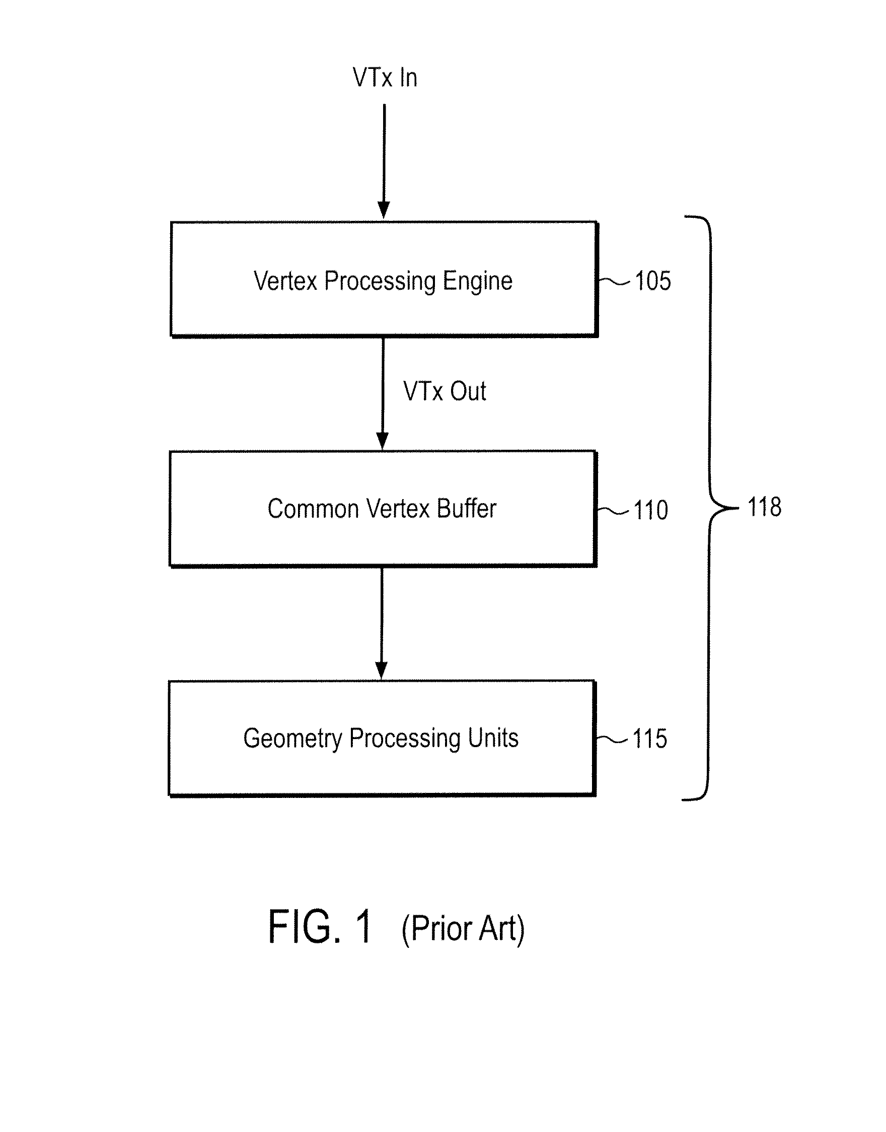
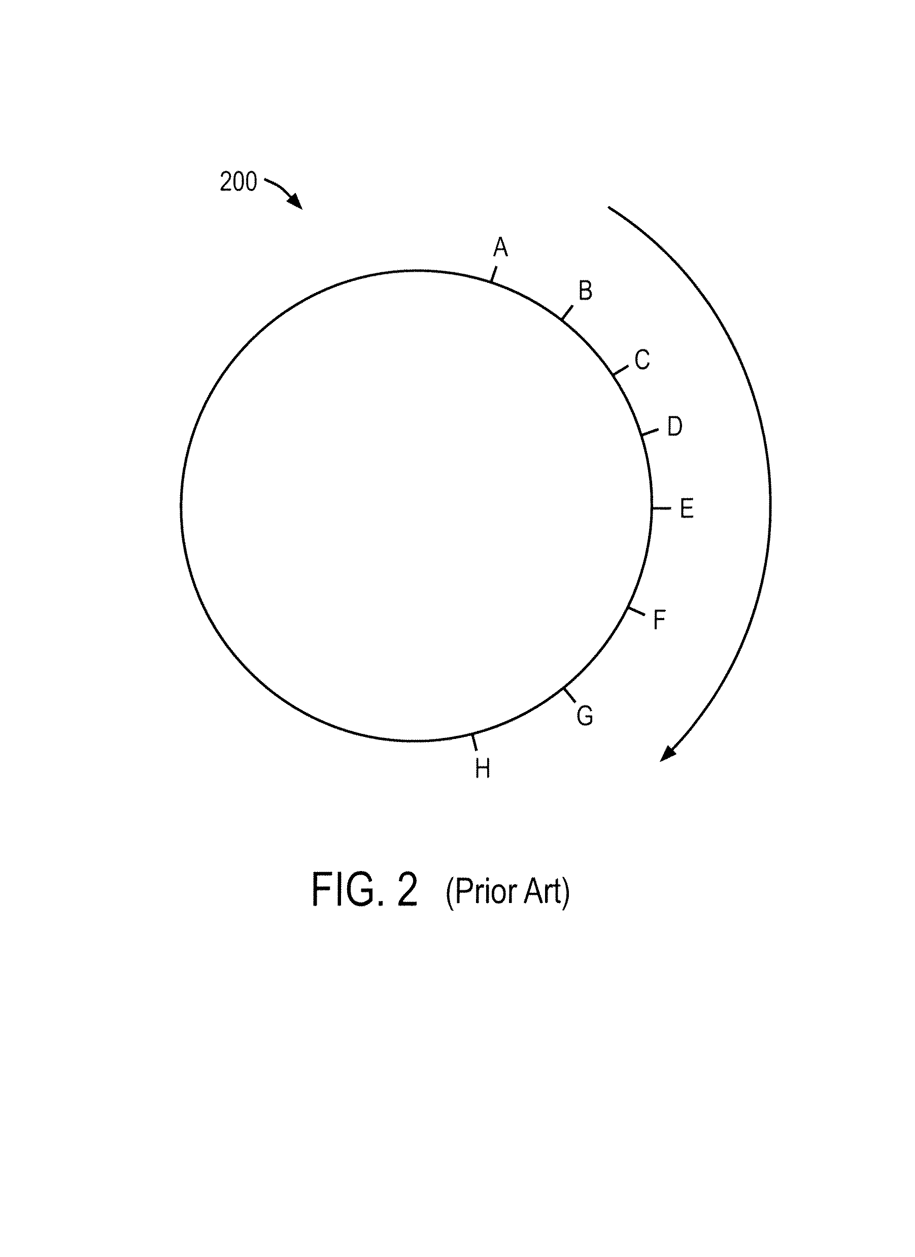
FIELD OF THE INVENTION[0001]The present invention is generally related to graphics technology for generating vertex and primitive information in a graphics system. More particularly, the present invention is directed towards generating vertex and primitive information in a graphics system having parallel downstream processing engines.BACKGROUND OF THE INVENTION[0002]Graphics processing is conventionally performed in a sequence of pipelined stages. There are a variety of different conventional pipeline architectures, depending on implementation details and the level of granularity that certain operations are described. However, conventionally the pipeline stages perform geometry processing and then pixel processing. The geometry processing stages may include, for example, transform and lighting. Additionally, geometry processing may include vertex shading.[0003]Referring to FIGS. 1 and 2, a prior art graphics processing architecture of the Nvidia Corporation of Santa Clara, Calif. in...

Claims


Application Information

Patent Timeline
Patent Type & Authority Patents(United States)
IPC IPC(8): G06F15/80G06F13/00G06T17/00
CPCG06T15/005G06T2210/52
Inventor MRAZEK, DANE T.BOWMAN, JAMES C.GAURIA, SAMEER M.
Owner NVIDIA CORP
Learn More