Vibrational excited frame food coating apparatus and methods of use thereof

a vibration-excited frame and food coating technology, which is applied in the field of vibration-excited frame food coating apparatus and the use of thereof, can solve the problems of reducing the free-flow properties of the coating mixture, presenting challenges to the machinery used to automatically and mechanically, and most automatic food coating processes fail to make “home-style” foods

Active Publication Date: 2010-04-27
VIBRATORY SOLUTIONS
View PDF46 Cites 17 Cited by
  • Summary
  • Abstract
  • Description
  • Claims
  • Application Information

AI Technical Summary

Benefits of technology

[0014]In another exemplary embodiment, the apparatus may further comprise: a second elongate pan having second proximal and distal portions, the second elongate pan mounted to the first elongate pan and adapted to feed coating to the first elongate pan, and, a waterfall distributor member mounted to the second elongate pan, the waterfall distributor including one or more transverse rows of a plurality of angular slots.
[0015]In another exemplary embodiment, the apparatus may further comprise: a screen located in the first distal portion and adapted to screen coating, a second elongate frame, a plurality of dampeners adapted to mount the first elongate frame to the second elongate frame, a soft roller adapted to be rotationally actuated by one or more ratchet assemblies, the ratchet assembly adapted to be engaged by the first elongate pan, a transverse blower assembly adapted to blow at least a portion of loose coating from the top of coated food product into the screen, and, a recycle assembly adapted to transfer screened coating to the first and second elongate pans, wherein the first and second elongate pans are adapted to vibrate having longitudinal and vertical vector components at a predetermined amplitude and frequency.

Problems solved by technology

While the automation of the food coating process is economically desirable, another goal of the food coating process is to make the coating appear to be “home-made.” However, most automatic food coating processes fail to make “home-style” appearing foods.
Each coating mixture has inherent characteristics that presents challenges to machinery used to automatically and mechanically coat food products.
For example, flour mixtures, which consist of finely ground dust-like particles, have a tendency to pack under pressure thereby decreasing the free-flow properties of the coating mixture around the food product, which can decrease coating uniformity.
Free-flowing mixtures in automated coating processes can often flow or leak out of the machinery.
Japanese-style crumbs have no uniform shape, are very delicate, and are crystalline-like in nature and appearance.
Principally, mechanical handling of the food items may be quite rigorous limiting its use to robust products.
More delicate food items (such as fish) may not be suitable for drum processing.
Steel wires (from which the belts are fabricated) are subject to breakage presenting the risk of contaminating the product.
Belt breakage can cause steel fines to be present in the coating mix and the final product.
Breakage also causes down-time to repair or replace belts.
In addition, other moving parts of the conveyor (including the rollers, guides and motors) are also subject to maintenance and repair, necessitating further down-time.

Method used


Image

  • Vibrational excited frame food coating apparatus and methods of use thereof
  • Vibrational excited frame food coating apparatus and methods of use thereof
  • Vibrational excited frame food coating apparatus and methods of use thereof

Examples


Embodiment Construction

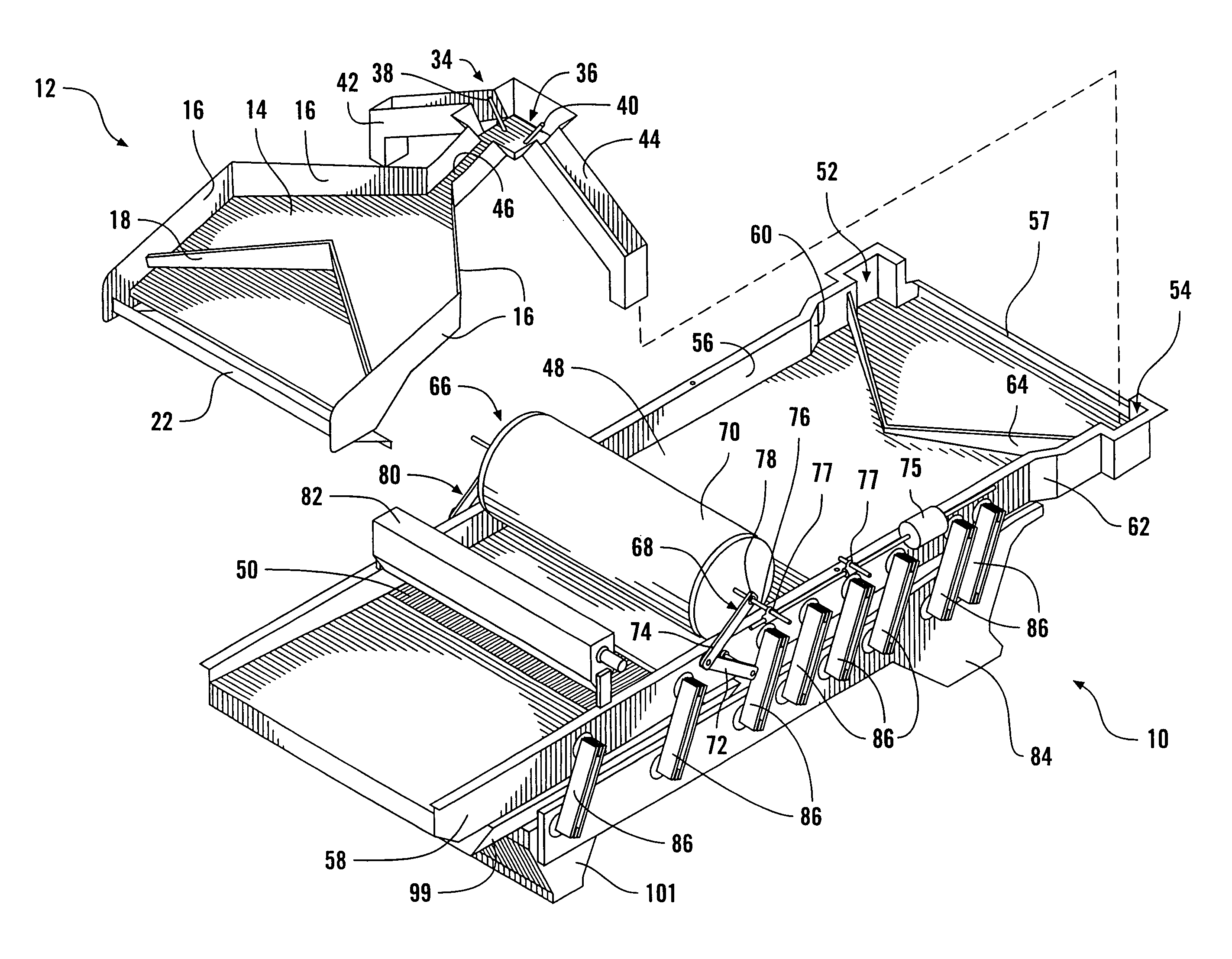
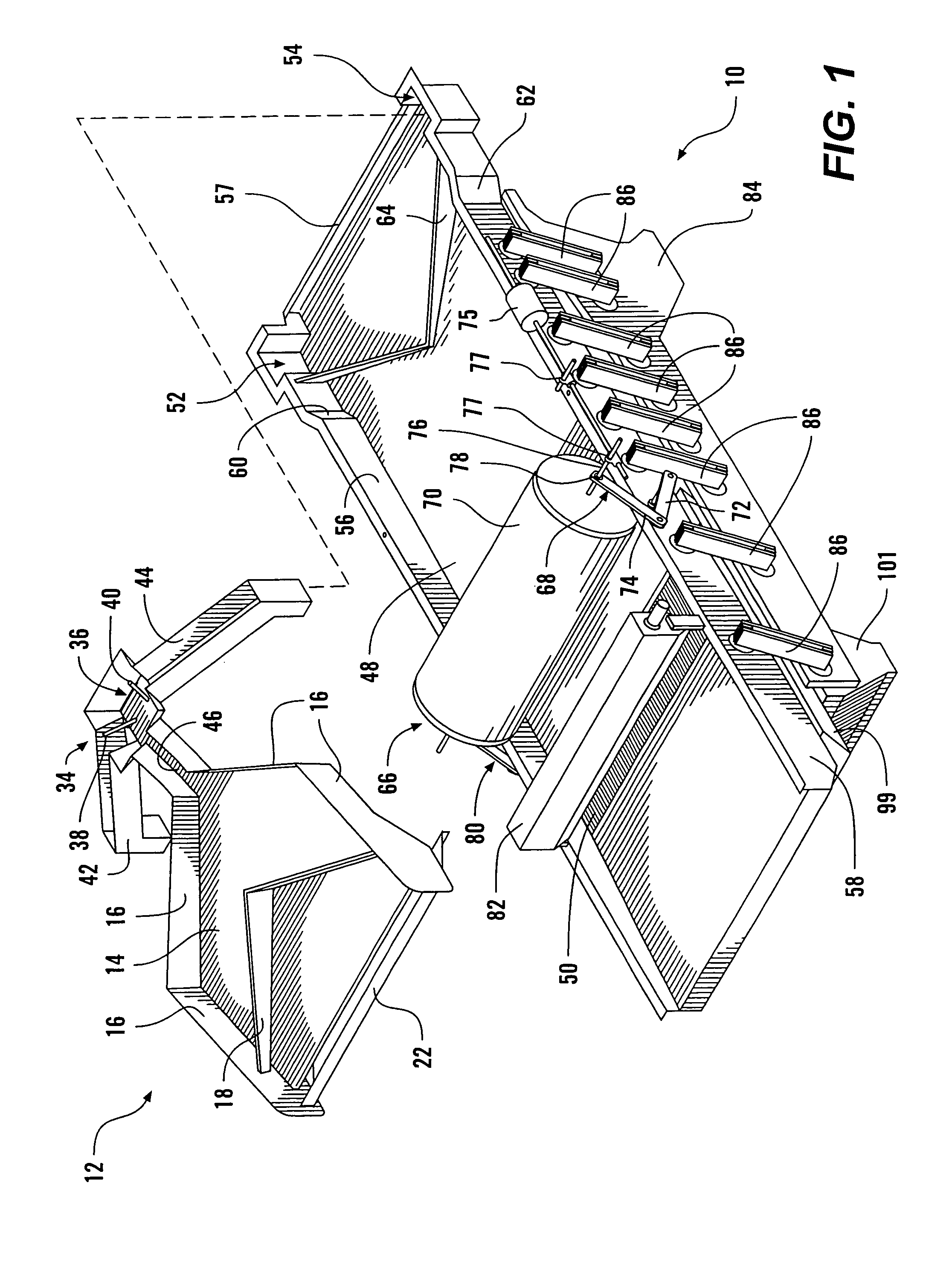
[0043]As shown in FIG. 1, a preferred embodiment of the invention includes an excited frame assembly 10 and an upper elongate pan assembly 12. The upper elongate pan assembly is mounted to the excited frame assembly 10.

[0044]The upper elongate pan assembly 12 includes an upper pan 14 having sidewalls 16 to contain a coating, such as free-flowing aggregate breading. The assembly 12 further includes an upper transverse distribution means 18 preferably a tapered, angular, wall-like structure to facilitate distribution (i.e., transversely) of coating across the distal portion of the upper pan 14.

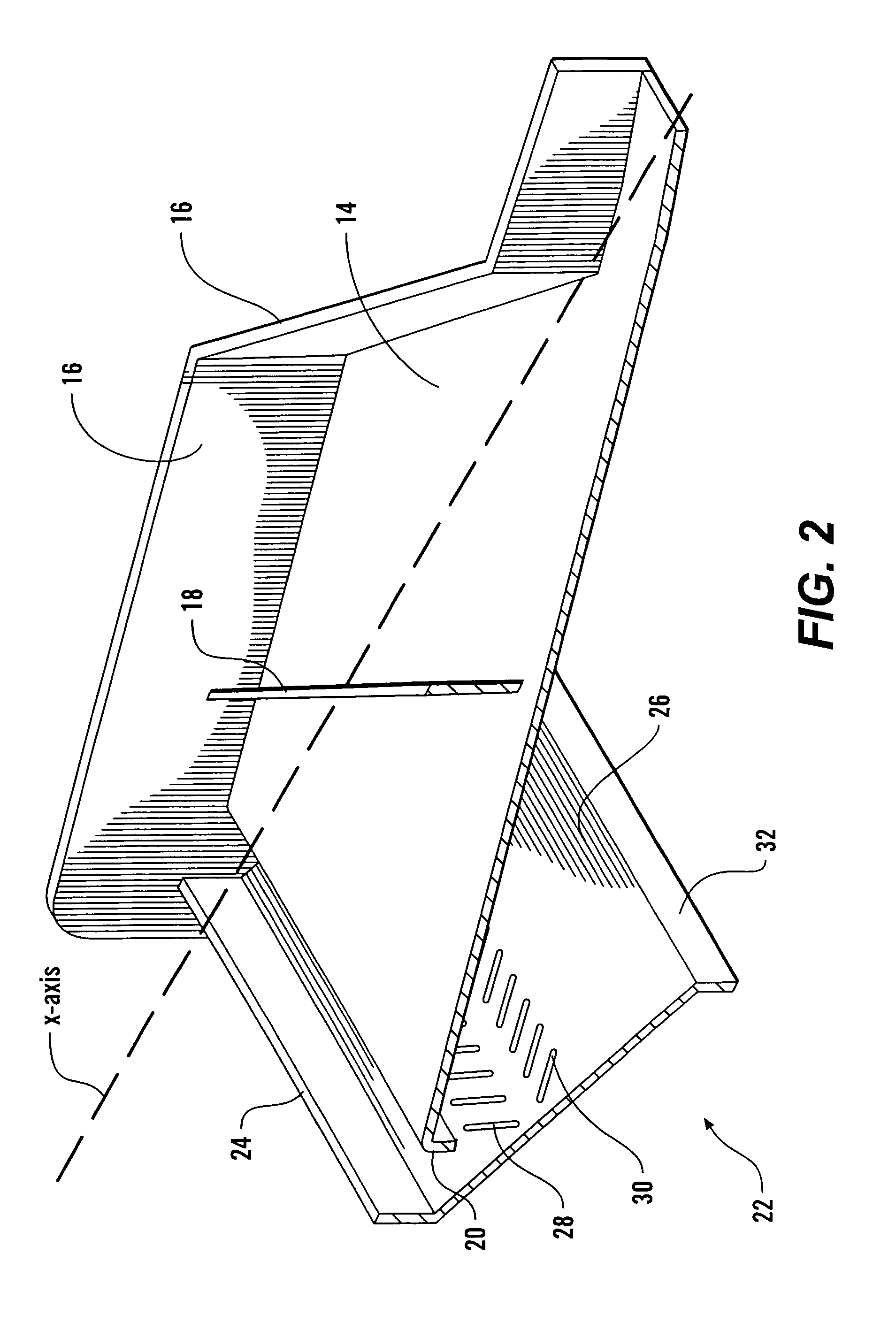
[0045]As shown in FIG. 2, a lip 20 is located at the distal end of the pan 14 to facilitate transfer of the coating from the upper pan 14 to a waterfall distributor member 22. The waterfall distributor member 22 includes a proximal lip 24 to direct aggregate coating leaving the distal end of the pan 14 toward a distribution surface 26 of the member 22. The distribution portion 26 includes qty. 2...


PUM


Abstract

The present invention is directed to an excited apparatus for coating food product with a coating. The apparatus includes an elongate pan having proximal and distal portions; a screen located in the distal portion and adapted to screen coating; an elongate frame; a motorized vibrator adapted to impart energy to the elongate frame at an angle β below horizontal; a plurality of springs mounting the elongate pan to the elongate frame, the springs being mounted at an angle θ above horizontal; another elongate frame; a plurality of dampeners mounting the two elongate frames; another elongate pan having proximal and distal portions, the elongate pan mounted to the other elongate pan and adapted to feed coating to the other elongate pan; a soft roller rotationally actuated by a ratchet assembly, the ratchet assembly engaged by the elongate pan; and, a recycle assembly for transferring screened coating to the elongate pans, wherein the elongate pan's vibrations have longitudinal and vertical vector components at a predetermined amplitude and frequency. The excited apparatus further includes a waterfall distributor member mounted to the elongate pan, the waterfall distributor including one or more transverse rows of a plurality of angular slots.

Description

REFERENCE TO RELATED APPLICATIONS[0001]This application incorporates material included in Disclosure Document No. 555929 filed Jun. 28, 2004, incorporated by reference herein in its entirety. This application further claims priority to U.S. Provisional Patent Application No. 60 / 667,405 filed Apr. 1, 2005.FIELD OF THE INVENTION[0002]The field of invention includes food coating and conveying equipment.BACKGROUND OF THE INVENTION[0003]Prepared food products come in a wide variety of styles. Many prepared food products, whether ready-to-eat or those needing further cooking, are prepared with a coating that makes the food product more appealing. Such prepared food products include entrees, appetizers, deserts (such as donuts), etc., and includes both meats and vegetables. The types of coatings used on these food products include dry coatings such as flour, bread crumbs, corn meal and the like. While the automation of the food coating process is economically desirable, another goal of the...

Claims


Application Information

Patent Timeline
Patent Type & Authority Patents(United States)
IPC IPC(8): B05C3/00
CPCA23G3/2076A23P1/082A23L1/005A23P20/12
Inventor BAKOS, JAMESKARPINSKY, JAMESROSE, SCOTTRENKLY, TRAVIS
Owner VIBRATORY SOLUTIONS
Why Eureka
Try Eureka