Exhaust system

a technology of exhaust system and exhaust pipe, which is applied in the direction of combustion engines, machines/engines, mechanical equipment, etc., can solve the problems of significant effects of state on the internal torque, and achieve the effects of reducing the necessary space for installation, increasing variability, and increasing torqu

Active Publication Date: 2010-04-27
EBERSPACHER EXHAUST TECH GMBH & CO KG
View PDF24 Cites 41 Cited by
  • Summary
  • Abstract
  • Description
  • Claims
  • Application Information

AI Technical Summary

Benefits of technology

[0005]The prior-art exhaust system is advantageously operated such that the sound transmission means is active at low rpms. Mufflers that are assigned to the exhaust gas lines are designed acoustically for interfering frequencies, which appear at low rpms. The sound transmission means is deactivated at higher rpms, as a result of which the effective interfering frequencies are reduced by half based on the specific assignment of the separate exhaust gas lines to individual cylinders of the internal combustion engine. Effective muffling can thus be achieved for two rpm ranges, which are related to one another via the interfering frequencies. The drawback is the limitation of the muffling action to only two rpm ranges. Furthermore, the activation of the sound transmission means at low rpms may lead to a reduction of the available engine torque because of disadvantageous effects on the charge cycle operation in the cylinders of the internal combustion engine.
[0006]This is where the present invention comes in. The present invention has the object of providing, for an exhaust system of the type mentioned in the introduction, an improved embodiment, which is characterized especially in that, for example, more torque is available at low rpms of the internal combustion engine and / or that an increased variability can be achieved for the adaptation of the muffling action and / or that the necessary space needed for installation is reduced.
[0007]This object is accomplished according to the present invention by the subject of the independent claim. Advantageous embodiments are the subject of the dependent claims.
[0008]The present invention is based on the general idea that the two exhaust gas lines can be acoustically coupled with two switchable sound transmission means, which are arranged at spaced locations from one another in the direction of flow of the exhaust gas. Increased variability can be achieved hereby for the switching states that can be set. At least three different switching states, namely, a first switching state, in which both sound transmission means are deactivated, a second switching state, in which one sound transmission means is activated while the other sound transmission means is deactivated, and a third switching state, in which both sound transmission means are activated, are of increased interest. It was found that the different switching states have significant effects on the torque of the internal combustion engine equipped with the exhaust system. In particular, the torque can increase markedly in the first switching state when this switching state is assigned to low rpms of the internal combustion engine, i.e., in operating states in which a high torque is especially desirable. Furthermore, it was found that the muffling action of the exhaust system can also be better adapted to different operating states of the internal combustion engine due to the three different switching states. However, it is particularly advantageous that, depending on the design of the switching states, the muffling action of the exhaust system as a whole can be improved to such an extent that a middle muffler may be eliminated in certain applications. The problems associated with the installation of a middle muffler in terms of the space needed for installation can be avoided as a result.
[0009]An embodiment in which the first sound transmission means located upstream is deactivated in the second operating state while the second sound transmission means located downstream is activated has proved to be particularly advantageous. The torque can be increased, for example, for medium rpms, in the second switching state.
[0010]A control means expediently assigns the switching states to different rpm ranges. The first switching state is assigned to a lower rpm range, while the second switching state is assigned to a medium rpm range and the third switching state is assigned to an upper rpm range.

Problems solved by technology

It was found that the different switching states have significant effects on the torque of the internal combustion engine equipped with the exhaust system.

Method used


Image

  • Exhaust system
  • Exhaust system

Examples


Embodiment Construction

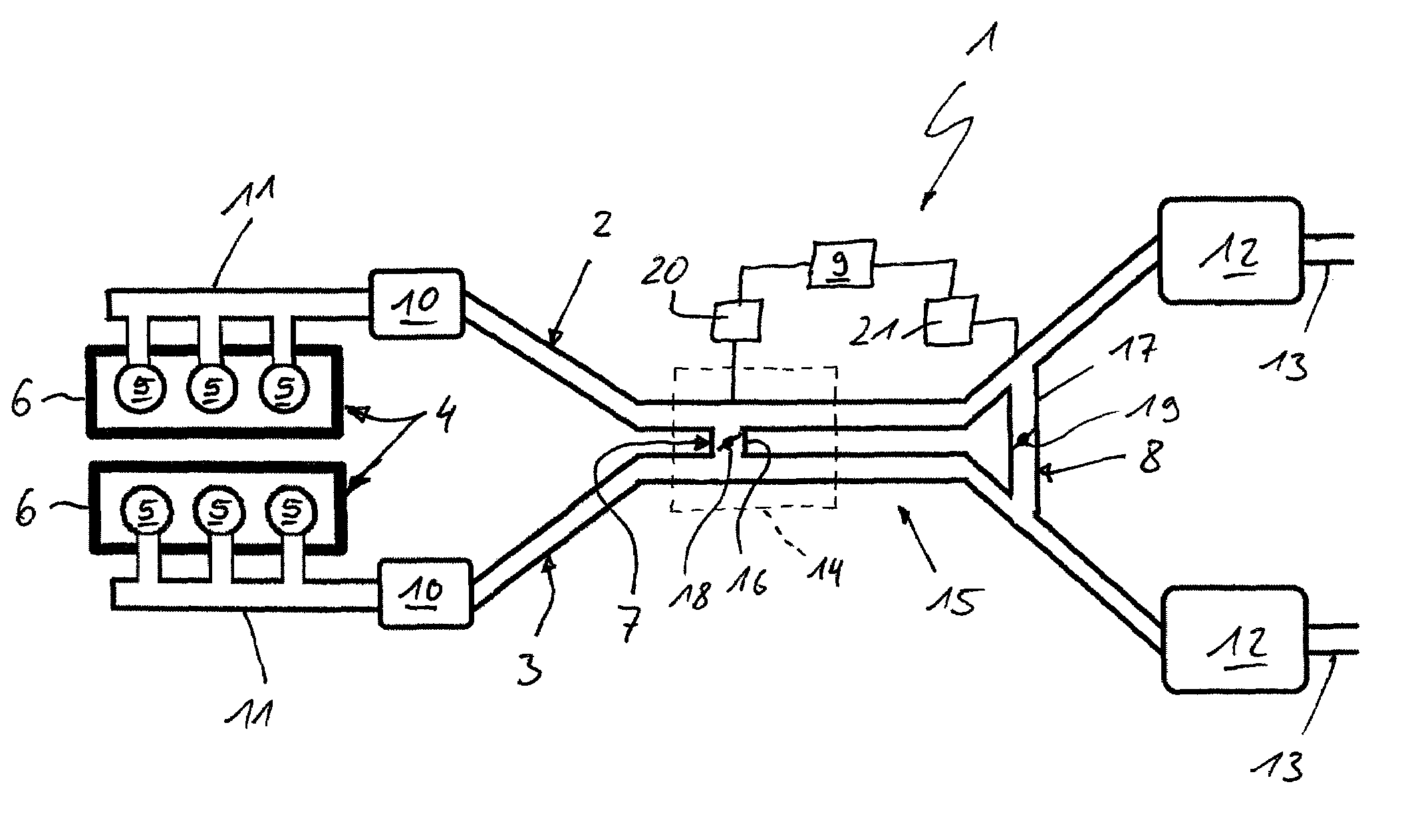
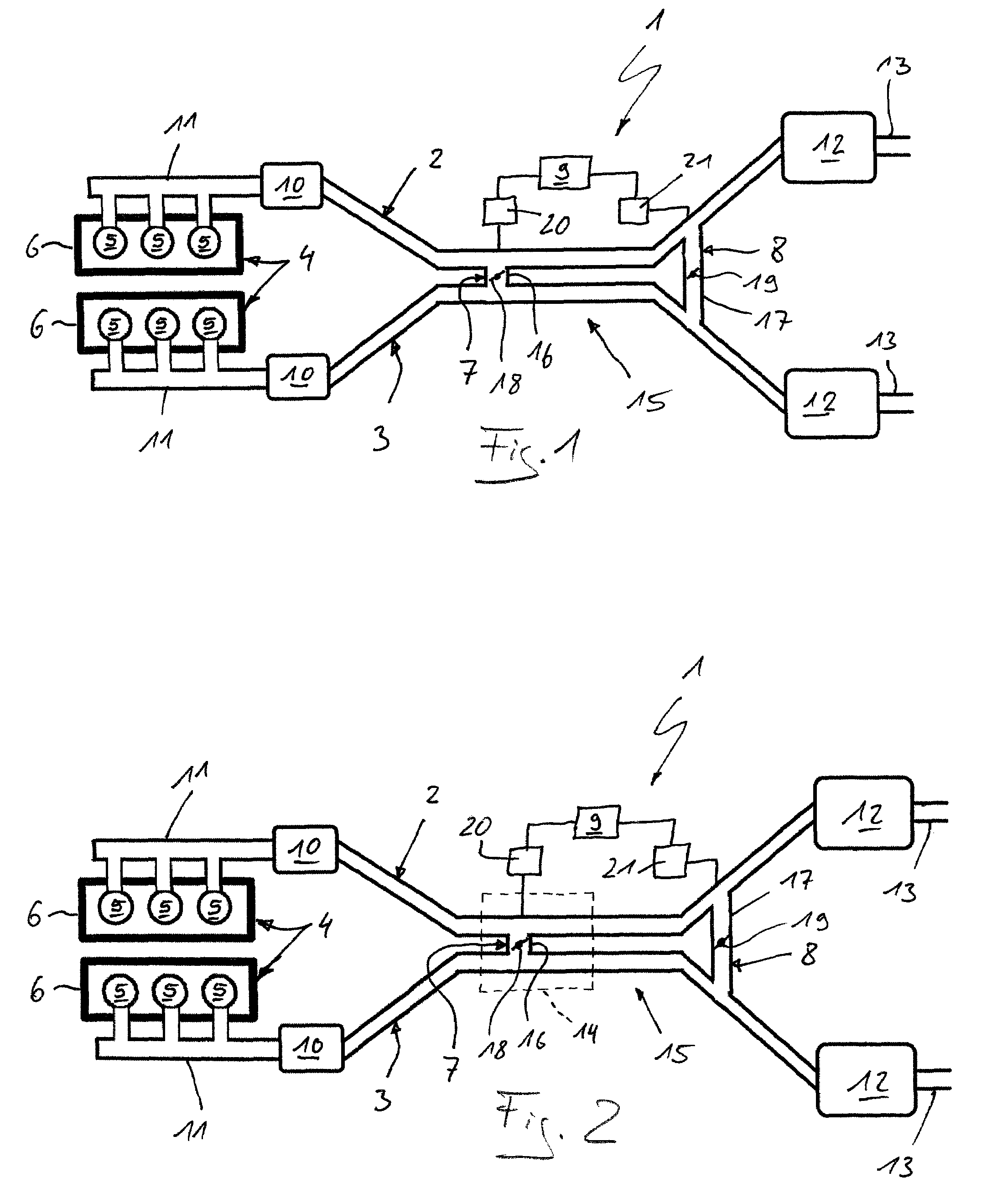
[0015]Referring to the drawings in particular, corresponding to FIGS. 1 and 2, an exhaust system 1 comprises two separate exhaust gas lines 2 and 3. The exhaust system 1 is used to remove the exhaust gases in an internal combustion engine 4, which may be arranged especially in a motor vehicle. The two exhaust gas lines 2, 3 are assigned here to different cylinders 5 of the internal combustion engine 4. Without limitation of the general scope, a six-cylinder engine is shown in the example. The two exhaust gas lines 2, 3 are generally assigned to a group of cylinders 5 each in a preferred design, the groups being selected such that the cylinders 5 of one group of cylinders and the cylinders 5 of the other group of cylinders have their working strokes alternatingly.

[0016]The group of cylinders may likewise be selected such that cylinders operating in parallel are always arranged in different groups of cylinders. This applies especially to larger engines, such as V-8 or V-12 engines.

[00...


PUM


Abstract

An exhaust system (1) is provided for an internal combustion engine (4), especially in a motor vehicle, with two separate exhaust gas lines (2, 3) with a first sound transmission feature (7), which couples the two exhaust gas lines (2, 3) with one another, and with a control (9) for activating and deactivating the first sound transmission connection (7) as a function of at least one operating parameter of the internal combustion engine (4). To improve the muffling behavior, a second sound transmission connection (8) is provided, which couples the two exhaust gas lines (2, 3) with one another downstream of the first sound transmission connection (7), and makes possible, depending on the particular operating parameter, three switching states (SZ), namely, a first switching state, in which both sound transmission connections (7, 8) are deactivated, a second switching state, in which only one sound transmission connection (7, 8) is activated, and a third switching state, in which both sound transmission connections (7, 8) are activated.

Description

CROSS REFERENCE TO RELATED APPLICATIONS[0001]This application claims the benefit of priority under 35 U.S.C. §119 of German Patent Application DE 10 2007 026 812.4 filed Jun. 6, 2008, the entire contents of which are incorporated herein by reference.FIELD OF THE INVENTION[0002]The present invention pertains to an exhaust system for an internal combustion engine, especially in a motor vehicle, with two separate exhaust gas lines for removing exhaust gases of the internal combustion engine.BACKGROUND OF THE INVENTION[0003]In passenger cars with high-performance internal combustion engines, which are preferably designed as V-engines, the exhaust gases are frequently sent from the two cylinder banks via two manifolds in two exhaust gas lines to a common end muffler or to two separate end mufflers. The two exhaust gas lines extend here in the vehicle on the underbody in a tunnel, which has heat protective shields at regularly spaced locations upwardly and to the side. The ground clearanc...

Claims


Application Information

Patent Timeline
Patent Type & Authority Patents(United States)
IPC IPC(8): F01N1/06F02B27/02F01N1/00F01N1/02F01N13/08
CPCF01N13/02F01N13/011F01N13/08F01N13/107
Inventor KRUGER, JANJESS, MARCO
Owner EBERSPACHER EXHAUST TECH GMBH & CO KG
Why Eureka
Try Eureka