Constant-velocity drive system for gimbaled rotor hubs

a rotor hub and constant-speed technology, which is applied in the direction of aircraft navigation control, vertical landing/take-off aircraft, transportation and packaging, etc., can solve the problems of increasing the size of the torque-splitting mechanism and the two-gimbal device, increasing the overall size of the two-gimbal device, and affecting the flight of the aircraft. , to achieve the effect of minimizing negative dynamic effects and increasing torqu

Active Publication Date: 2012-12-25
TEXTRON INNOVATIONS
View PDF7 Cites 5 Cited by
  • Summary
  • Abstract
  • Description
  • Claims
  • Application Information

AI Technical Summary

Benefits of technology

[0028]There is a need for an improved constant-velocity drive system which allows transfer of increased torque while minimizing negative dynamic effects and meeting component sizing / packaging requirements.
[0029]Therefore, it is an object of the present invention to provide an improved constant-velocity drive system which allows transfer of increased torque while minimizing negative dynamic effects and meeting component sizing / packaging requirements.
[0031]The present invention provides significant advantages, including: (1) providing an improved constant-velocity drive system with reduced negative dynamic effects for rotary-wing aircraft, (2) allowing transfer of more torque through a differential torque-splitting mechanism, and (3) providing a robust structural means for connecting a differential torque-splitting mechanism and a double-gimbal mechanism where the differential torque-splitting mechanism is axially spaced from the double-gimbal mechanism.

Problems solved by technology

While the constant-velocity drive systems taught by Zoppitelli et al. may be suitable for smaller, lighter, less powerful rotary-wing aircraft, significant limitations become apparent when the constant-velocity drive systems taught by Zoppitelli et al. are considered for use in larger, heavier, more powerful rotary-wing aircraft.
Additionally, since the two-gimbal device associated with the torque-splitting mechanism substantially envelopes the torque-splitting mechanism, the overall size of the two-gimbal device would also necessarily increase.
Clearly, increasing the size of the torque-splitting mechanism and the two-gimbal device taught by Zoppitelli et al. is not desirable and does not provide a satisfactory solution for providing a constant-velocity drive system for a larger, heavier, more powerful rotary-wing aircraft.

Method used


Image

  • Constant-velocity drive system for gimbaled rotor hubs
  • Constant-velocity drive system for gimbaled rotor hubs
  • Constant-velocity drive system for gimbaled rotor hubs

Examples


Embodiment Construction

[0053]The present invention is an improved constant-velocity drive system for a rotary-wing aircraft which provides improved torque transfer while minimizing negative dynamic characteristics. While specific reference is made to using the present invention with tilt-rotor rotary-wing aircraft, the present invention may alternatively be used with any other rotary-wing vehicle / craft.

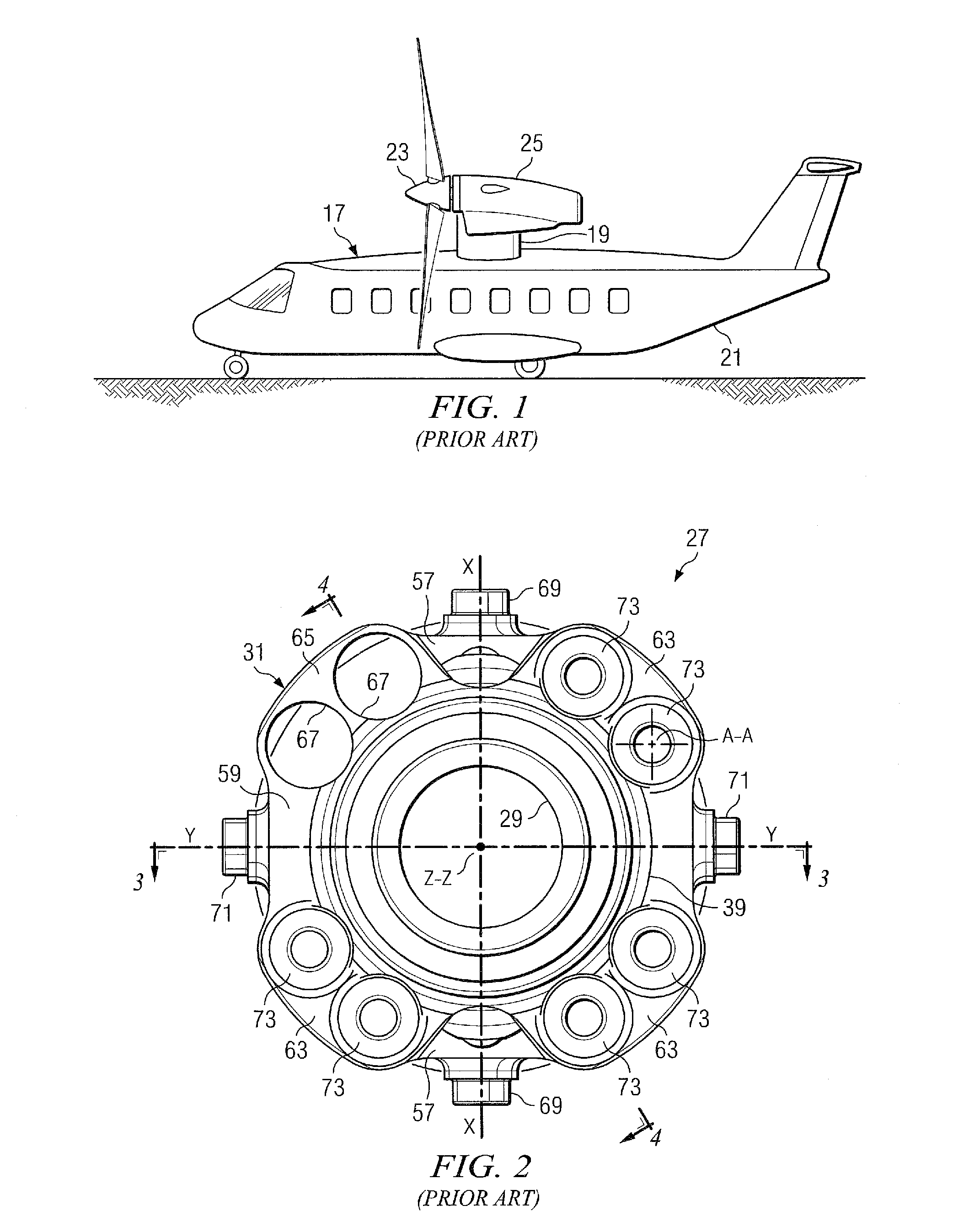
[0054]FIG. 9 depicts a tilt-rotor, rotary-wing aircraft incorporating the constant-velocity drive system of the present invention. FIG. 9 illustrates a tilt-rotor aircraft 201 in an airplane mode of flight operation. When in airplane mode, wings 203 are utilized to lift craft body 205 in response to the action of rotor systems 207, 209. Each rotor system 207, 209 is illustrated as having four rotor-blades 211. Each of nacelles 213, 215 (along with associated spinning covers 216) substantially enclose a constant-velocity drive systems 217, obscuring constant-velocity drive systems 217 from view in FIG. 9. Of...


PUM


Abstract

A constant-velocity drive system for a rotary-wing aircraft rotor comprising a differential torque-splitting mechanism and a gimbal mechanism is disclosed. A rotary-wing aircraft having a rotary-wing aircraft rotor comprising a differential torque-splitting mechanism and a gimbal mechanism is disclosed.

Description

TECHNICAL FIELD[0001]The present invention relates to the field of rotary-wing aircraft having gimbaled rotor hubs.DESCRIPTION OF THE PRIOR ART[0002]Consumer demand is increasing for rotary-wing aircraft to provide more thrust, higher speeds, and carry heavier loads and / or heavier fuselages. For example, there is a demand for more powerful tilt-rotor aircraft. Of course, where performance criteria such as those listed above are to be increased, the functional systems of the rotary-wing aircraft must be improved to provide the desired resultant performance enhancements. The rotor hub drive system is one of the many functional systems which requires improvement in order to meet the demand for improved rotary-wing aircraft performance.[0003]Rotor hub drive systems often are / include constant-velocity drive systems, or homokinetic drive systems, which have been in use for a very long time. There are numerous successful designs of constant-velocity drive systems for various types of rotar...

Claims


Application Information

Patent Timeline
Patent Type & Authority Patents(United States)
IPC IPC(8): B64D35/00B64C27/52
CPCB64C29/0033F16C1/04B64C27/52B64C27/41
Inventor RAUBER, RICHARDSTAMPS, FRANK B.BRASWELL, JR., JAMES LEE
Owner TEXTRON INNOVATIONS
Why Eureka
Try Eureka