Dual auger shredder having low profile

a dual-auger, low-profile technology, applied in the direction of shaping presses, manufacturing tools, grain treatment, etc., can solve the problems of large-scale shredder systems that may not be designed to handle larger loads, system requirements a significant amount of space to operate, and the type of large-scale shredder systems may reach undesirable heights, etc., to achieve low profile, more torque, and slower speed

Active Publication Date: 2015-07-23
KOMAR IND LLC
View PDF25 Cites 4 Cited by
  • Summary
  • Abstract
  • Description
  • Claims
  • Application Information

AI Technical Summary

Benefits of technology

[0009]Exemplary embodiments may overcome some or all of the aforementioned disadvantages of the known art. One exemplary embodiment may provide a shredding system having a relatively low profile compared to known systems for shredding large scale items. One embodiment may eliminate the need to discharge the shredded material out of the bottom of the unit. For example, one embodiment is a dual screw auger system that has an outlet that is substantially in line with the axis of one of the augers. Consequently, such an embodiment may be adapted to discharge the shredded material directly into a standard roll-off container or a semi-trailer, or onto a conveyor, without unnecessarily elevating the shredder system above the ground. An exemplary embodiment may also comprise at least one tapered auger screw to achieve a desired degree of shredding of large scale items at a desired rate. For instance, an exemplary embodiment may comprise twin opposing tapered augers, which may operate at slower speeds, with more torque, to more efficiently and safely shred large scale items as compared to known straight screw systems. Furthermore, exemplary embodiments may comprise fixed or variable speed drive(s). For example, the use of variable speed drives may facilitate metering of the output shredded material. Exemplary embodiments may also be adapted to adjust the rate and / or direction of rotation of each auger, either in unison or independently. An exemplary embodiment may also comprise an input mechanism associated with the processing chamber that facilitates the introduction of large scale items. One example may comprise a drop hopper wall of sufficient dimensions to receive and rotate large scale items (e.g., oversize crates) into the processing chamber. In such an embodiment, the drop hopper wall may be located at a significantly lower height as compared to known systems for shredding large scale items. Another embodiment may include an elongated hopper associated with the processing chamber, which facilitates the introduction of large scale items.

Problems solved by technology

As a result, such systems demand a significant amount of space to operate.
Consequently, these types of large scale shredder systems may reach undesirable heights for many applications.
On the other hand, some known systems may not be designed to be able shred larger loads (e.g., large crates, pallets, furniture, appliances, drums, telephone poles, railroad ties, etc.).
For instance, some known system may not have sufficient size or screw characteristics.
As a result, larger loads may need to be manually broken down in these instances, which is time and cost intensive.
Known shredder systems may also not be able to shred material at a desirable rate or to a desirable degree.
Such systems may not be able to efficiently shred large scale items.

Method used


Image

  • Dual auger shredder having low profile
  • Dual auger shredder having low profile
  • Dual auger shredder having low profile

Examples


Embodiment Construction

)

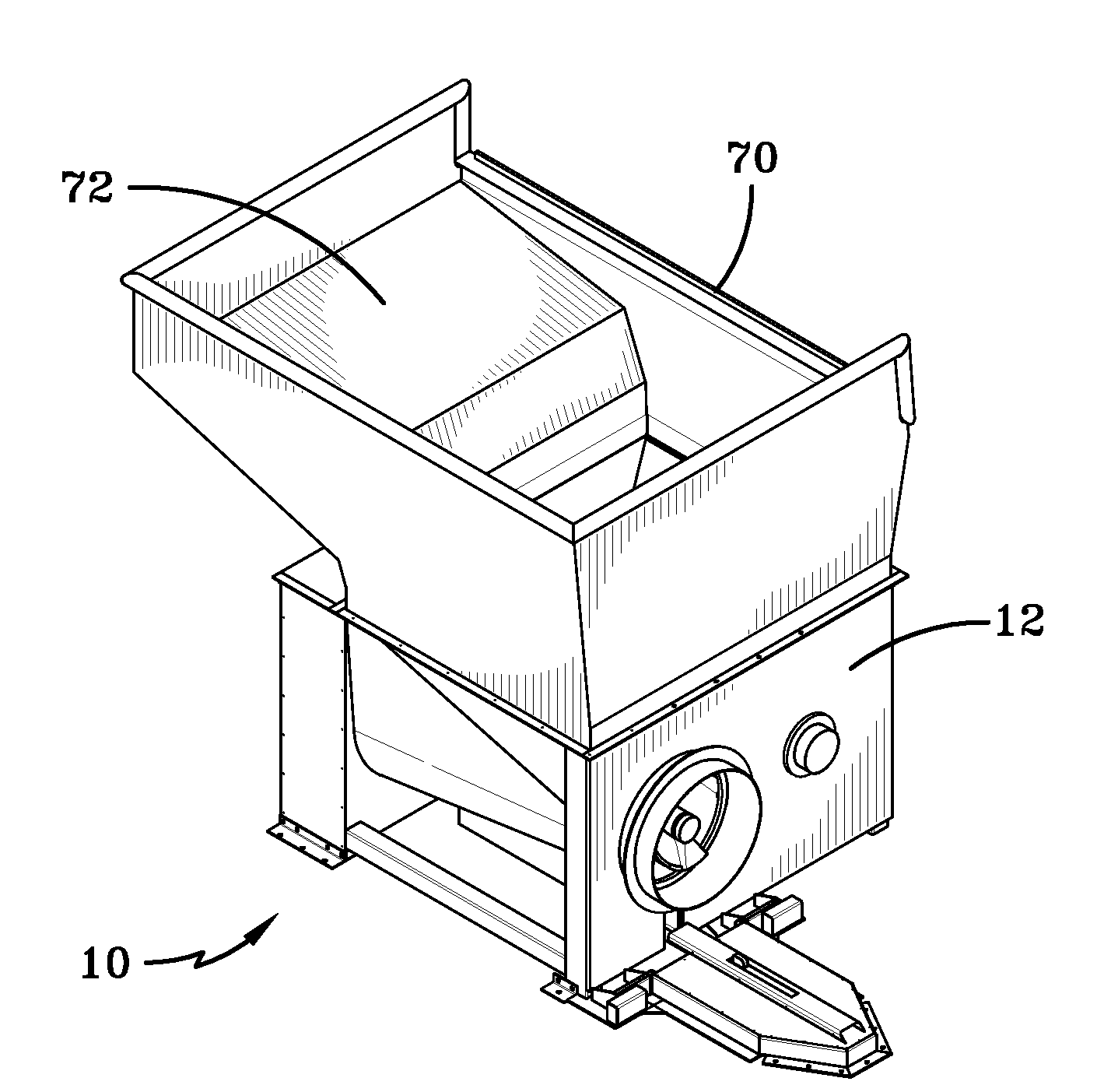
[0022]Exemplary embodiments of the present invention are directed to a shredder system and method for operation. Exemplary embodiments may be particularly beneficial for shredding large scale items such as oversize crates, pallets, furniture, appliances, drums, telephone poles, railroad ties, and other large scale items. However, it is not intended to limit the invention to the shredding of any particular type of material unless expressly set forth otherwise.

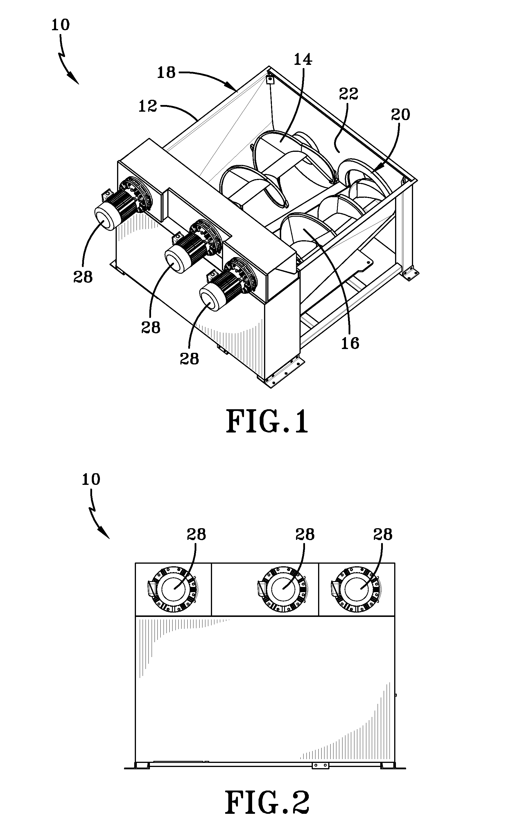
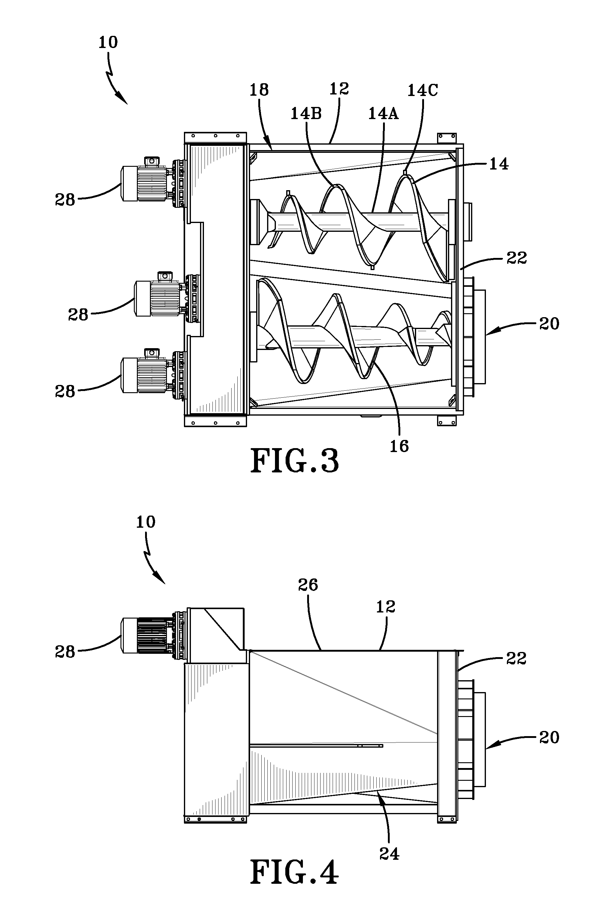
[0023]FIGS. 1-6 show various views of one exemplary embodiment of a shredder system. In this example, system 10 is comprised of a processing chamber 12 and twin opposing tapered augers 14 and 16, which are positioned in processing chamber 12. The processing chamber 12 may include an input opening 18 that is adapted to receive material to be shredded. The opposed combination of augers 14 and 16 may then shred the material. In particular, an exemplary embodiment of the opposing augers 14 and 16 may be particularly beneficial for ...


PUM


Abstract

An auger system adapted to shred large materials. An exemplary embodiment is comprised of dual opposing augers that are adapted to grab, compress, and shred the material, reducing the material size such that it may be discharged through a side outlet opening and/or an extrusion tube into, for example, a standard roll-off compaction container. An exemplary embodiment allows large material to be processed in a low speed device with reduced equipment dimensions, providing operator safety with low profile loading, lower noise level, reduced chances of material being expelled from the processing chamber, and ability to use conventional material transport (e.g., semi-trucks).

Description

[0001]This application claims the benefit of U.S. Provisional Application No. 61 / 910,893, filed Dec. 2, 2013, which is hereby incorporated by reference in its entirety.BACKGROUND AND SUMMARY OF THE INVENTION[0002]Exemplary embodiments of the present invention relate generally to a multiple auger system adapted for shredding various types of materials (e.g., waste).[0003]Examples of known shredder systems may require the material to be transported to an undesirably high location (e.g., 20 feet or higher) in order to be input to the shredder system. Moreover, known systems may have material delivery systems or procedures that need to be designed to transport the material to higher locations to allow for larger material loads to be input to the shredder system. As a result, such systems demand a significant amount of space to operate.[0004]Oftentimes, the height of the shredder system is necessary to allow room for discharge of the shredded material from the bottom of the system. For e...

Claims


Application Information

Patent Timeline
Patent Type & Authority Applications(United States)
IPC IPC(8): B02C19/22B02C18/00B02C23/02
CPCB02C19/22B02C18/0084B02C23/02B30B11/243B02C18/142B02C2201/06
Inventor KOENIG, MARK E.KOENIG, LARRY E.
Owner KOMAR IND LLC
Why Eureka
Try Eureka