Rotational grip twist machine and method for fabricating bulges of twisted wire electrical connectors

a technology of twisted wire and twisting machine, which is applied in the direction of line/current collector details, electrical apparatus, and connection formation by deformation, etc., can solve the problems of reducing the speed of fabricating twisting pins, and achieve the effects of reducing the number of twisting pins

Inactive Publication Date: 2005-12-06
MEDALLION TECH
View PDF61 Cites 3 Cited by
  • Summary
  • Abstract
  • Description
  • Claims
  • Application Information

AI Technical Summary

Benefits of technology

[0024]One improved aspect of the present invention involves forming bulges in helically coiled wire in manner such a manner that allows twist pins to be more rapidly and more efficiently fabricated compared to previous techniques. Another improved aspect of the present invention involves fabricating twist pins having more uniform, more controlled, more precisely positioned and more symmetrically shaped bulges. Another improved aspect of the present invention involves fabricating bulges and twist pins without using reciprocal motions. The lost motion of return strokes and the latenc

Problems solved by technology

The lost motion of return strokes and the latency associated with

Method used


Image

  • Rotational grip twist machine and method for fabricating bulges of twisted wire electrical connectors
  • Rotational grip twist machine and method for fabricating bulges of twisted wire electrical connectors
  • Rotational grip twist machine and method for fabricating bulges of twisted wire electrical connectors

Examples


Embodiment Construction

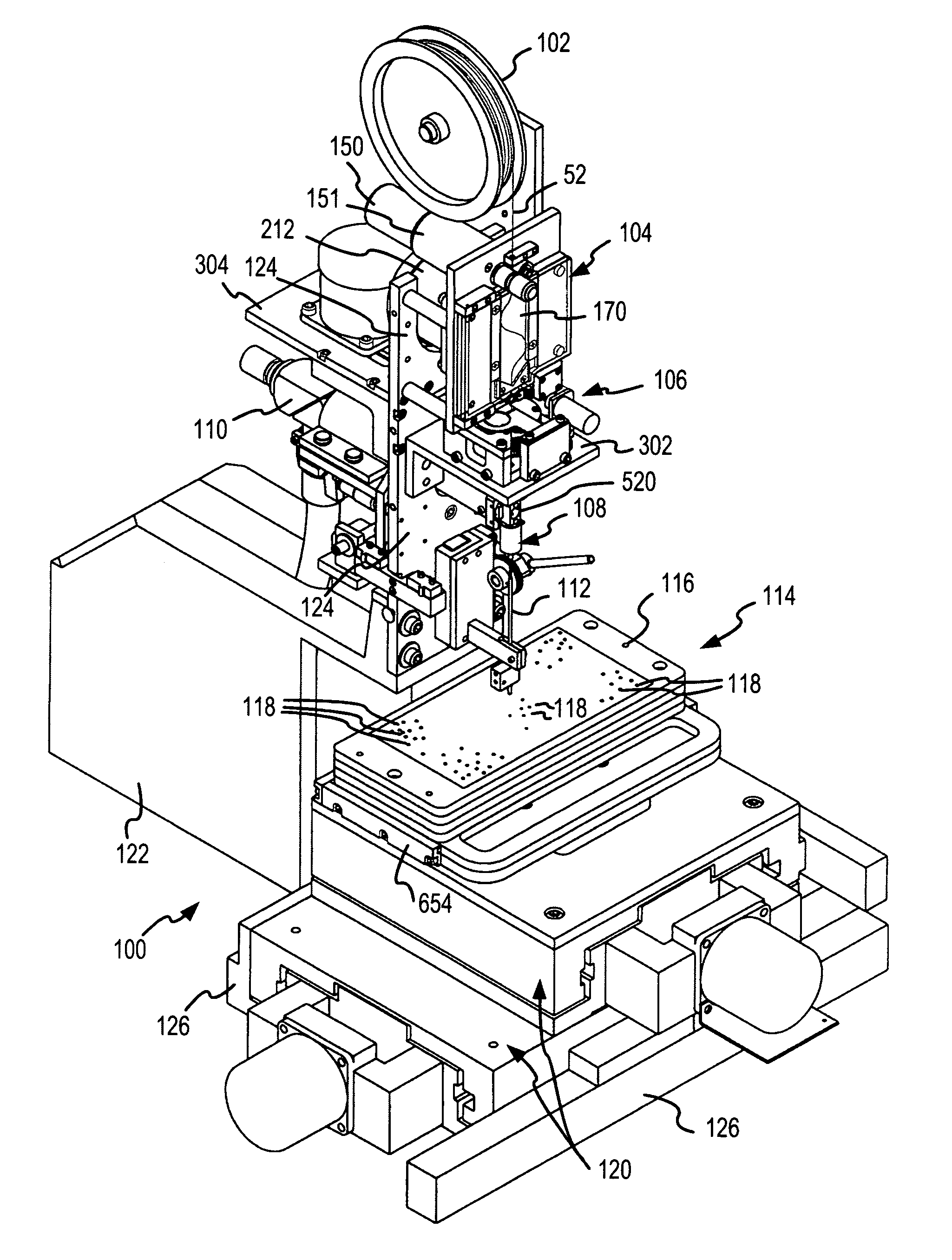
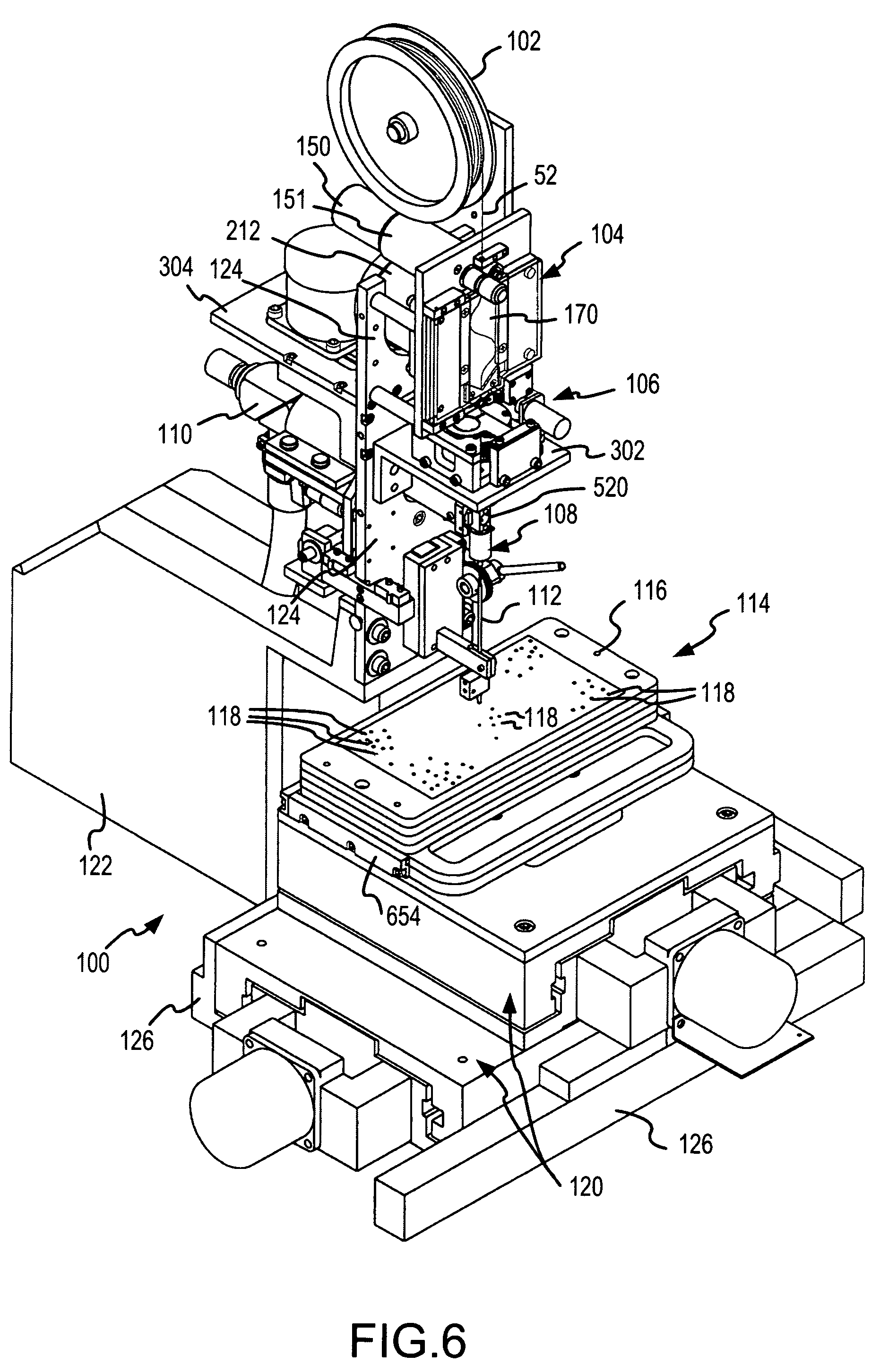
[0056]The present invention is preferably incorporated in an improved machine 100 which fabricates twist pins 50 (FIG. 1), and an improved methodology for fabricating bulges 58 (FIG. 1) of twist pins, as shown and understood by reference to FIG. 6. The twist pins are fabricated from the gold-plated, beryllium-copper wire 52 which is wound on a spool 102. A wire feed mechanism 104 of the machine 100 unwinds the wire 52 from the spool 102 and accurately feeds the wire to a bulge forming mechanism 106 which is located below the wire feed mechanism 104. The bulge forming mechanism forms the bulges 58 (FIG. 1) at precise locations along the length of the wire 52. The positions where the bulges 58 are formed are established by the advancement of the wire 52 by the wire feed mechanism 104. The bulge forming mechanism 106 forms the bulges by gripping the wire 52 and untwisting the wire in the reverse or anti-helical direction.

[0057]After all of the bulges of the twist pin 50 (FIG. 1) have b...


PUM

PropertyMeasurementUnit
Lengthaaaaaaaaaa
Timeaaaaaaaaaa
Thicknessaaaaaaaaaa

Abstract

Bulges in a wire having helically coiled strands are formed by untwisting the strands in an anti-helical direction at a predetermined position, to form an electrical connector from a length of the stranded wire. The wire is gripped by moving two spaced apart clamp members to a closed position and thereafter rotating the clamp members relative to one another in at least one complete relative revolution in a direction which is anti-helical relative to the coiled strands to form the bulge. The wire is gripped and rotated in the anti-helical direction for a relative rotational interval of greater than one-half, and preferably three-fourths, of a complete relative revolution. Thereafter, during the remaining rotational interval of each relative revolution, the clamp members are opened to permit the wire to be advanced to the next position where a bulge is to be formed.

Description

CROSS-REFERENCE TO RELATED INVENTION[0001]This invention is a division of U.S. application Ser. No. 09 / 782,888, filed Feb. 13, 2001, filed by the inventors herein, for a Rotational Grip Twist Machine and Method for Fabricating Bulges of Twisted Wire Electrical Connectors, now U.S. Pat. No. 6,729,026. This invention and application is also related to inventions for High-Speed, High-Capacity Twist Pin Connector Fabricating Machine and Method, Wire Feed Mechanism and Method Used for Fabricating Electrical Connectors, and Pneumatic Inductor and Method of Electrical Connector Delivery and Organization, described in U.S. patent applications Ser. Nos. 09 / 782,987; 09 / 782,991; and 09 / 780,981, respectively, now U.S. Pat. Nos. 6,584,677, 6,530,511, and 6,528,759, respectively, all of which are assigned to the assignee hereof, and all of which have at least one common inventor with the present application. The disclosures of these U.S. Patents are incorporated herein by this reference.FIELD OF ...

Claims


Application Information

Patent Timeline
IPC IPC(8): H01R43/28
CPCH01R43/28H01R12/523Y10T29/49222Y10T29/4914Y10T29/49218Y10T29/5187Y10T29/5121Y10T29/5193H01R43/04B21F7/00
Inventor GARCIA, STEVEN E.HARDEN, JR., JAMES A.
Owner MEDALLION TECH
Why Eureka
Try Eureka