Slide mounting bracket structure

a technology for mounting brackets and slides, which is applied in the direction of building scaffolds, lighting support devices, doors/windows, etc., can solve the problems of prior art displaying complexity and enormity in its structure, and it is difficult to demount a single slide and bracket of a server from an array of slides and brackets of servers, so as to boost the value of the fitting of the apparatus and minimize the structure

Active Publication Date: 2010-04-27
KING SLIDE WORKS CO LTD
View PDF14 Cites 79 Cited by
  • Summary
  • Abstract
  • Description
  • Claims
  • Application Information

AI Technical Summary

Benefits of technology

[0025]a minimized structure in a limited space operates in an optimized way, which substantially boosts the value of the fitting of the apparatus.

Problems solved by technology

In the U.S. Pat. No. 6,891,727 B2, once a mounting bracket is setup, the demounting of it can only be approached from its lateral, which means it would possibly be hard to demount a single slide and bracket of a server from arrays of slides and brackets of servers.
Unfortunately, the prior art exhibits a complexity and enormity in its structure.

Method used


Image

  • Slide mounting bracket structure
  • Slide mounting bracket structure
  • Slide mounting bracket structure

Examples


Embodiment Construction

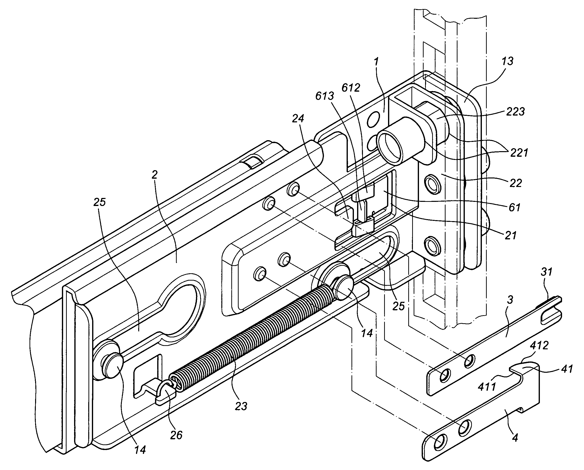
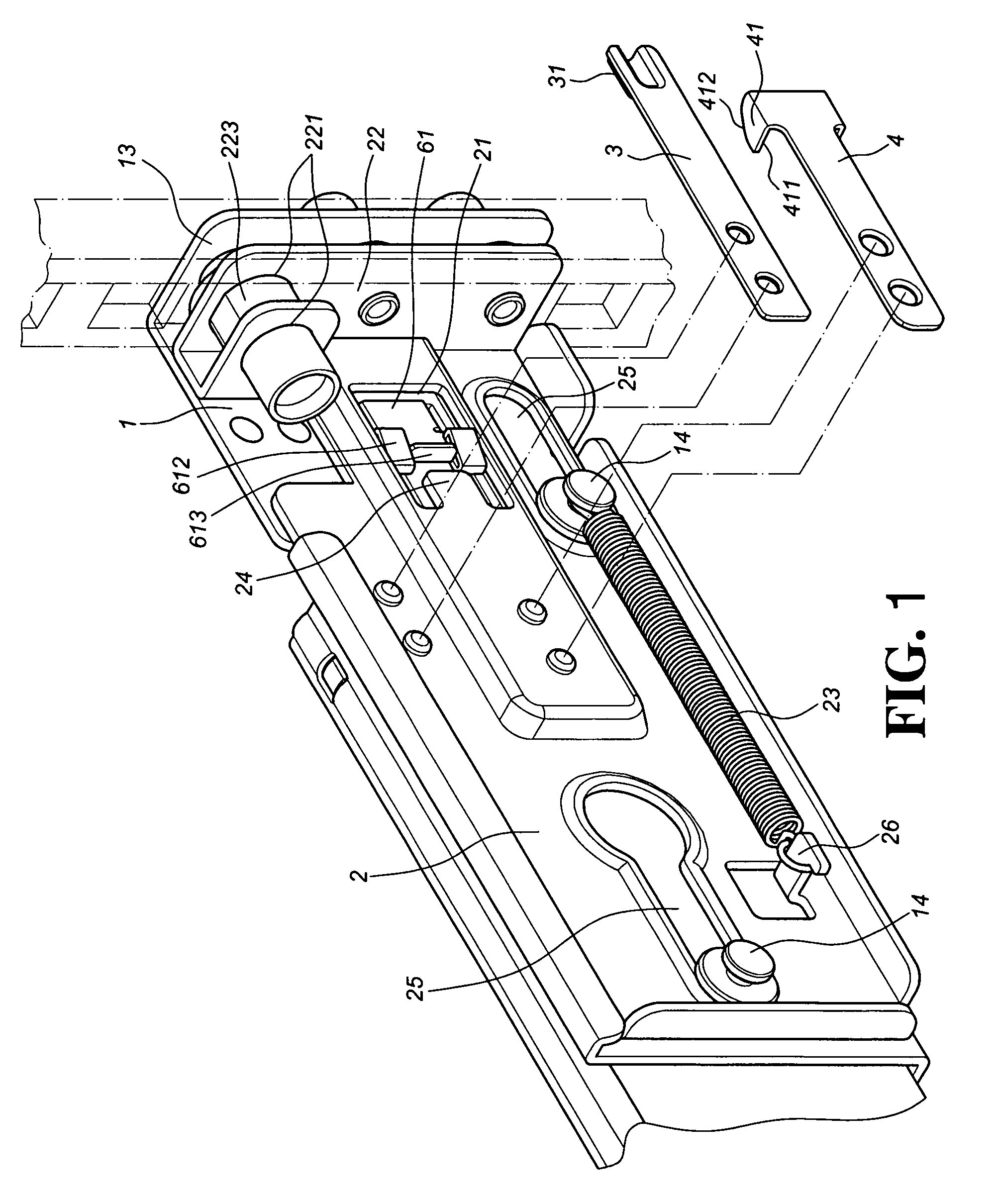
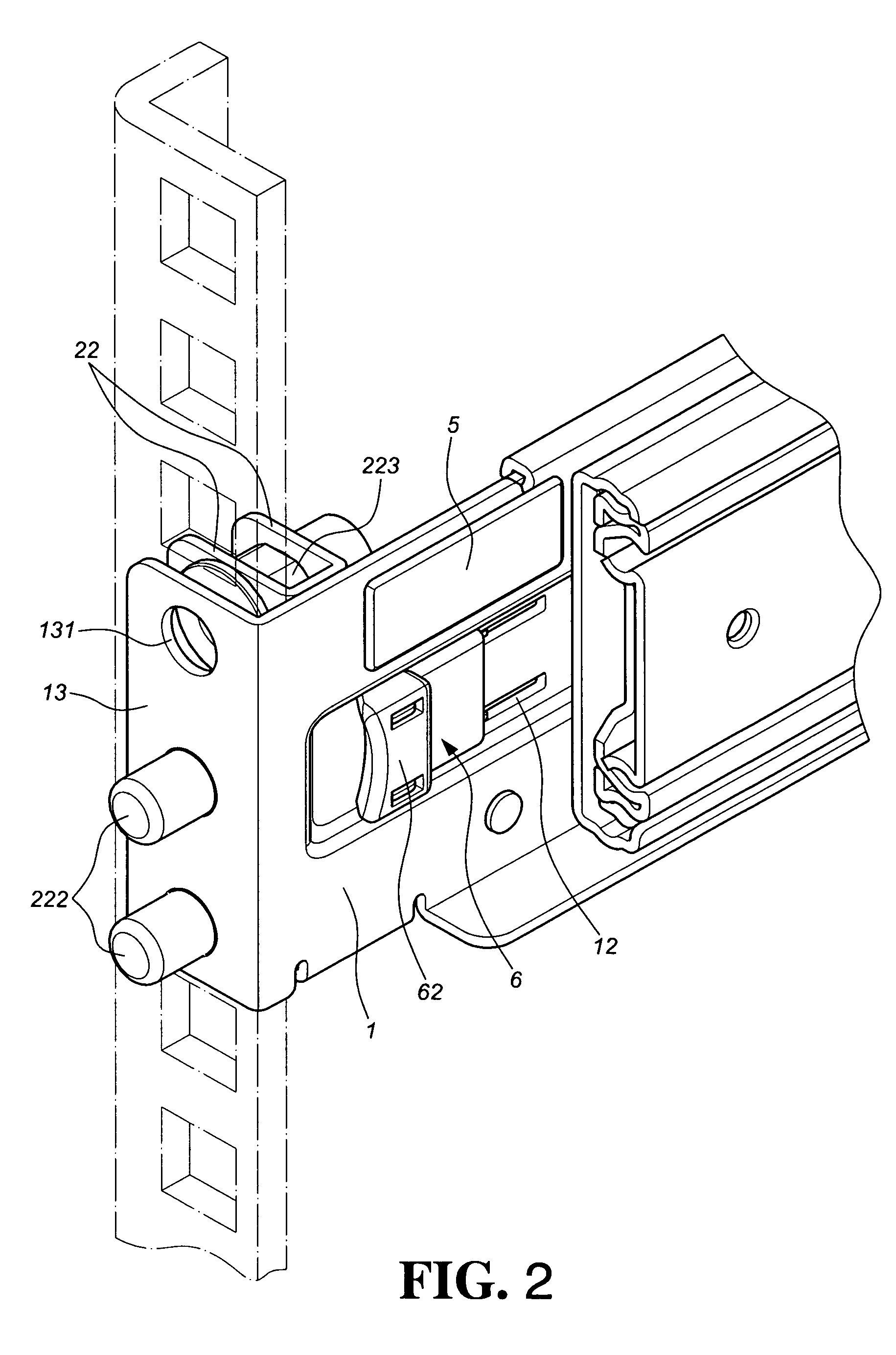
[0037]Please refer to FIGS. 1-3, which are three-dimensional diagrams of a preferred embodiment of the present invention, viewed from the outside and inside respectively, comprising a main bracket 1, an auxiliary bracket 2, a first engaging member 3, a second engaging member 4, an actuating element 5, and a linking member 6.

[0038]The main bracket 1 is provided with an opening 11, longitudinal troughs 12, a first folded plate 13 and clamps 14. Each longitudinal trough 12 has a blocking section 121. The first folded plate 13 is located at a front end of the main bracket 1 and provided with through holes 131.

[0039]The auxiliary bracket 2, referring to FIG. 4, is provided with a slot 21, a second folded plate 22, an elastic element 23, a raised slice 24, chutes 25 and a hook 26. The second folded plate 22 is located at a front end of the auxiliary bracket 2. The auxiliary bracket 2 is slidably coupled to the main bracket 1 at its outer side, and the sliding of the auxiliary bracket 2 is...


PUM


Abstract

A slide mounting bracket structure includes a main bracket, an auxiliary bracket, a first engaging member, a second engaging member, an actuating element, a linking member and an elastic element. The main bracket is provided with the actuating element and the linking member at its inner side, and the auxiliary bracket is provided with the first engaging member and the second engaging member at its outer side. The actuating element corresponds to the first engaging member. The linking member has a part penetrating the main bracket, and has a support stand corresponding to the second engaging member, which further drags the auxiliary bracket to engage in sliding, and brings a second folded plate to depart from a first folded plate.

Description

BACKGROUND OF THE INVENTION[0001]1. Field of the Invention[0002]The present invention relates to a slide mounting bracket structure, particularly to an auxiliary bracket that is capable of sliding relatively to a main bracket, which frees the tools for the attachment and removal of the slide promptly with respect to a rack.[0003]2. Description of the Prior Art[0004]A handy mounting of a bracket integrated with a slide to a metal rack is frequently viewed in the rack-mounted computer system.[0005]This category of the slide brackets, are quite copious in their designs; however, the leading trends recently come in features of tool-less and prompt mounting and demounting, such as U.S. Pat. Nos. 6,891,727 B2 and 7,192,103 B2.[0006]The foregoing disclosed prior art are focusing on a “sliding bracket” technique. In the U.S. Pat. No. 6,891,727 B2, once a mounting bracket is setup, the demounting of it can only be approached from its lateral, which means it would possibly be hard to demount ...

Claims


Application Information

Patent Timeline
Patent Type & Authority Patents(United States)
IPC IPC(8): A47F5/00A47H1/10
CPCA47B88/044A47B88/43
Inventor CHEN, KEN-CHINGHUANG, CHIEN-LIWANG, CHUN-CHIANG
Owner KING SLIDE WORKS CO LTD
Why Eureka
Try Eureka