Variable resistance exercise device

a resistance exercise and variable technology, applied in the field of variable resistance exercise devices, can solve problems such as some hardness, and achieve the effects of increasing resistance, easy assembly, and easy bendability

Active Publication Date: 2010-04-27
BROWN JR GORDON L
View PDF18 Cites 15 Cited by
  • Summary
  • Abstract
  • Description
  • Claims
  • Application Information

AI Technical Summary

Benefits of technology

[0003]It is a principal object of this invention to provide an elongated variable resistant flexible exercise device that is easy to assemble and which bends in any direction when performing exercises, the exercise device preferably includes a flexible tube having rounded interior in which an elongated rod with a rectangular cross section is inserted. When the exercise device is held by the user's hands at or near the ends of the device or positioned on a modified piece of exercise equipment, such as an ‘ParaBody 900 ST abdominal contractor’, and a force is applied to the ends of the device, or to the center of the device, the device will readily bend in the intended direction as increased resistance is provided, as the distance between the ends of the device is reduced, with a resulting enhancement of the strengthening, conditioning and toning of the targeted muscles.
[0004]It is an additional objective to provide for a greater degree of comfort to the user by having the exterior of the flexible elongated device deform slightly to an oval shape when bent such that the flat part of the oval shape spreads the resistance forces over a wider area of contact with the user's body producing a more comfortable feeling. This feature is due to the use of a flexible extruded thermoplastic tube having an essentially round section cavity into which the pultruded rod loosely fits such that when the thermoplastic tube bends its shape is altered to an oval.
[0005]A preferred embodiment features an extruded thermoplastic tubular component such as extruded PVC or a thermoplastic rubber tube that has a round or nearly round section cavity. The thermoplastic tube has a durometer such that the exercise device feels comfortable when placed onto the surface of a person's body such as the front of the person's thigh. It should not be too hard but can be somewhat hard given the fact that the thermoplastic tubular device will deform to an approximate oval cross sectional shape when bent. Into the cavity of the tube there is inserted a pultruded rod having, preferably, a consistent rectangular cross-section shape extending substantially the length of the extruded thermoplastic round tube. The rod fits easily into the cavity of the extruded thermoplastic round tube and is able to rotate freely about its longitudinal axis when inside the cavity of the straight extruded thermoplastic tube. End caps are placed on each end of the tube. When the tube is bent the rectangular section rod will automatically orient itself to bend about its major cross section axis.

Problems solved by technology

It should not be too hard but can be somewhat hard given the fact that the thermoplastic tubular device will deform to an approximate oval cross sectional shape when bent.

Method used


Image

  • Variable resistance exercise device
  • Variable resistance exercise device
  • Variable resistance exercise device

Examples


Embodiment Construction

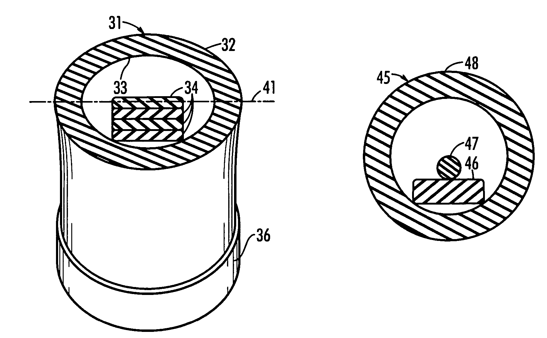
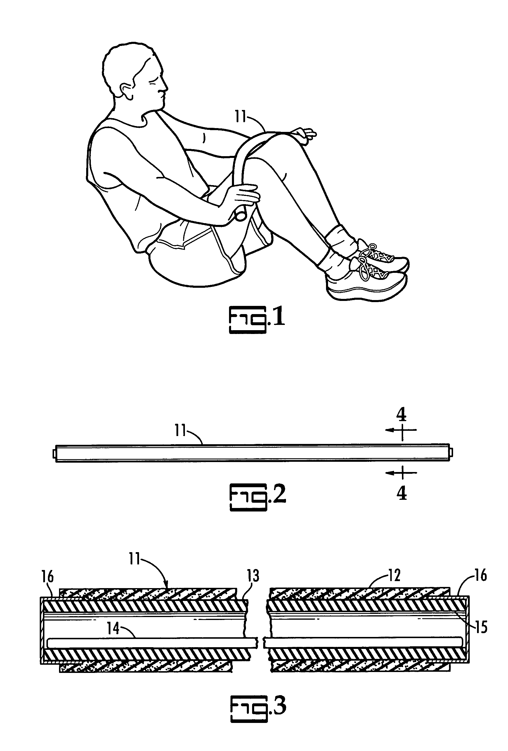
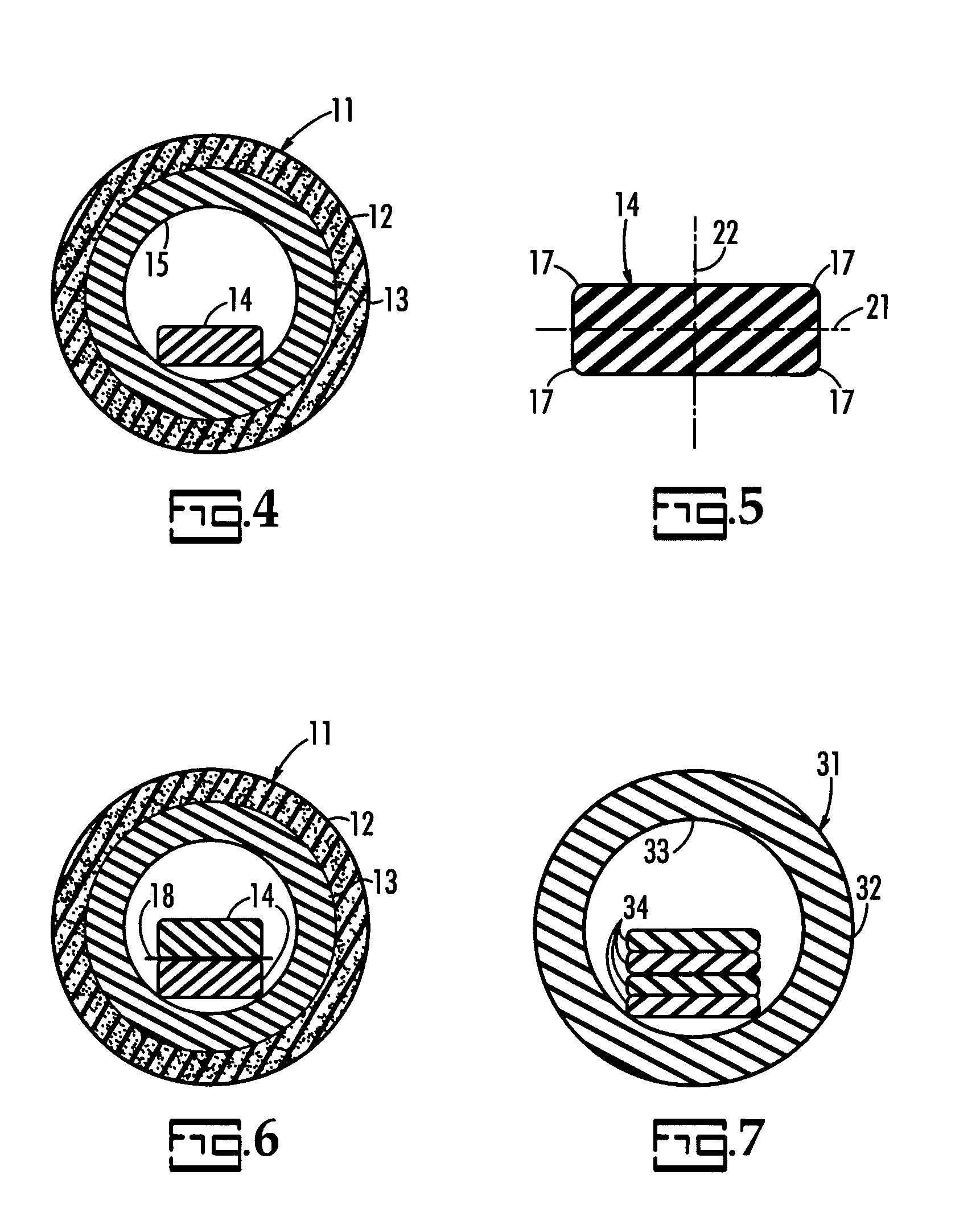
[0017]The invention is hereinafter described in detail by reference to the accompanying drawings. The invention is not intended to be limited to the embodiments described; rather, this detailed description is included to enable any person skilled in the art to produce a flexible elongated exercise device which will bend in any direction when each end is grasped by the user at or near each end with a force applied to each end of the device; or with the hands grasping each end and applying a force to each end with the center of the device pressed against a part of the body such as the thigh(s); or with the hand or hands positioned at or near the center of the device and the hands applying a force at or near the center of the device with the ends of the device positioned in contact with each of the thighs slightly above the knee.

[0018]A preferred embodiment of the flexible exercise device 11, shown in FIGS. 1-5, includes a soft foam plastic tubular sleeve 12, a cylindrical tube 13 and ...


PUM


Abstract

An exercise device for human exercise routines having an elongated pultruded plastic rod or rods fitting loosely within a plastic tube. At least one of the rods is rectangular in cross section and the tube may be covered by a soft foam plastic sleeve. The rod may be produced by the pultrusion process.

Description

RELATED APPLICATIONS[0001]The U.S. patent application Ser. No. 10 / 278,450 of Gordon L. Brown, Jr. filed Oct. 23, 2002 for an Abdominal Exercise Routine Using A Flexible Elongated Device discloses exercise routines for which this invention is particularly useful.FIELD OF INVENTION[0002]The disclosed invention relates to an apparatus designed to perform exercises intended to firm, strengthen and tone a person's abdominal muscles, arm muscles and other muscles of the body when the apparatus is bent, which creates a resistance for the targeted muscles. The disclosed apparatus defines a flexible elongated device which is easy for an individual to handle in that it bends in any direction in response to the forces applied to the ends of the device, or to the center of the device with the hands holding the ends, or to the ends of the device with the hand or hands positioned at or near the center of the apparatus. Also, as the apparatus bends the external shape of the apparatus changes sligh...

Claims


Application Information

Patent Timeline
Patent Type & Authority Patents(United States)
IPC IPC(8): A63B21/02
CPCA63B21/028A63B21/026
Inventor BROWN, JR., GORDON L.
Owner BROWN JR GORDON L
Why Eureka
Try Eureka