
Sun tracking solar panels

a solar panel and solar energy technology, applied in the field of solar energy tracking solar panels, can solve the problems of reduced efficiency of energy conversion units, difficulty or impracticality in achieving, and minimal efficiency reduction

Active Publication Date: 2010-04-27
BEAM GLOBAL
View PDF7 Cites 22 Cited by
  • Summary
  • Abstract
  • Description
  • Claims
  • Application Information

AI Technical Summary

Benefits of technology

"The present invention provides an apparatus for moving solar panels to track the movement of the sun to maximize solar energy utilization. The apparatus includes a plurality of solar panels with energy converting units mounted on them. The solar panel is supported on a mount that is fixed at an angle relative to the ground. A motor is provided to rotate the solar panel on the mount about a central axis. A controller is provided to control the rotation of the panel according to a programmed schedule. The apparatus allows for efficient tracking of the sun and maximizes solar energy utilization."

Problems solved by technology

This, however, may be difficult or impractical to achieve.
Although the efficiencies of energy converting units are diminished as the angle of incidence deviates from perpendicular; with only small deviations, the diminution of efficiency is minimal.
On the other hand, with relatively large deviations from the perpendicular, the diminished effect quickly becomes significant.

Method used


Image

  • Sun tracking solar panels
  • Sun tracking solar panels
  • Sun tracking solar panels

Examples


Embodiment Construction

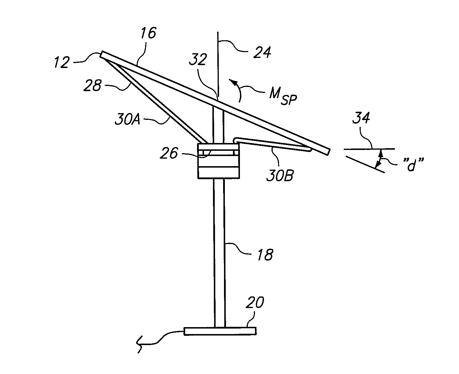
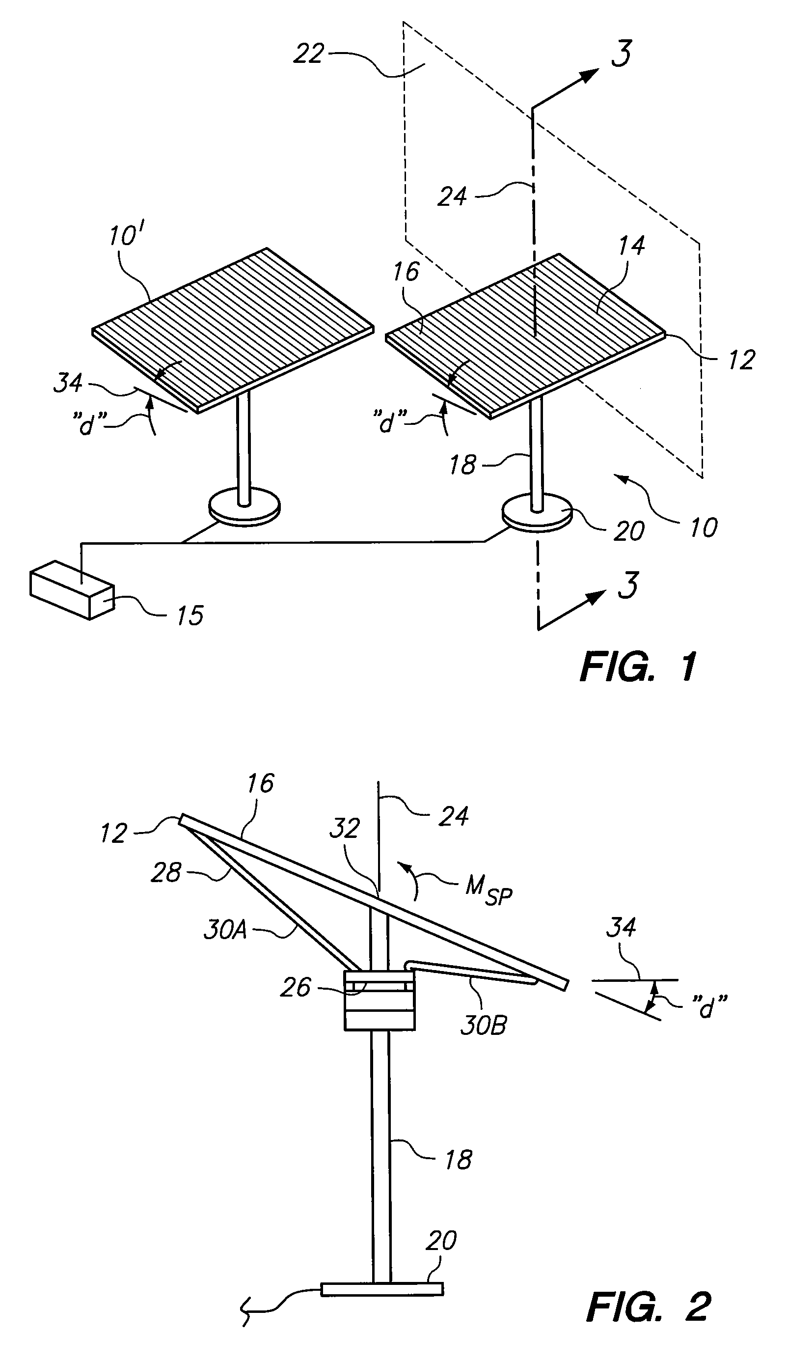
[0016]Referring initially to FIG. 1, an apparatus in accordance with the present invention is shown, and is generally designated 10. Another apparatus 10′ is shown in FIG. 1 to indicate that a plurality of apparatuses 10 can be combined together in a functional array. As shown in FIG. 1, each apparatus 10 includes a solar panel 12 that supports a plurality of energy converting units 14. For the present invention, the preferred energy converting unit 14 is a photovoltaic cell of a type well known in the pertinent art. The energy converting unit 14, however, may be of any type device that is useful for converting solar energy into electrical energy for use at a utility site 15 such as thermal-solar cells or concentrating cells.

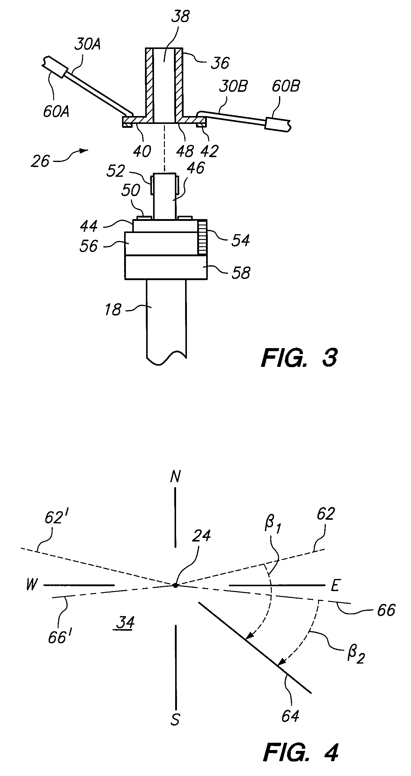
[0017]FIG. 1 further indicates that the energy converting units 14 are mounted on a surface 16 of the solar panel 12. Additionally, FIG. 1 shows that the solar panel 12 is supported on a pole 18 that is somehow anchored to the ground by a base 20. For purposes o...


PUM


Abstract

A system is provided for maximizing solar energy utilization by moving a solar panel to track movement of the sun from sunrise to sunset. Preferably, the solar panel is inclined from the horizontal plane by a fixed angle of about ten degrees. And, movements of the solar panel are accomplished, daily, in accordance with a programmed schedule of consecutive cycles. In this schedule, each cycle has a start time (i.e. sunrise) and a start point that is determined by the sun's direction from the solar panel.

Description

FIELD OF THE INVENTION[0001]The present invention pertains generally to systems that employ energy converting units, such as photovoltaic cells, to harness solar energy. More particularly, the present invention pertains to systems in which energy converting units are mounted on solar panels that track movement of the sun during daylight hours. The present invention is particularly, but not exclusively useful as a system of solar panels wherein the panels are inclined relative to the horizontal plane, and are moved in accordance with a programmed daily schedule to maximize solar energy utilization.BACKGROUND OF THE INVENTION[0002]The angle at which solar radiation is incident on an energy converting unit (e.g. a photovoltaic cell) can significantly affect the unit's ability to convert solar energy into electrical energy. Optimally, the angle of incidence for solar radiation will be ninety degrees (i.e. an energy converting unit is oriented so solar radiation is directed at a right an...

Claims


Application Information

Patent Timeline
Patent Type & Authority Patents(United States)
IPC IPC(8): G01C21/02H01J40/14H01J5/16F24S23/79
CPCG01S3/7861F24J2/5406F24J2/523Y02E10/47F24S25/10F24S30/422
Inventor NOBLE, ROBERT L.ADELSON, WILLIAM S.
Owner BEAM GLOBAL
Learn More