Camera module with improved leaf spring attachment

a technology of camera module and leaf spring, which is applied in the field of camera module, can solve the problems of predetermined welding strength and partial peeling of the upper leaf spring from the top surface, and achieve the effect of stable load characteristic and sufficient bonding strength

Inactive Publication Date: 2010-04-27
MITSUMI ELECTRIC CO LTD
View PDF8 Cites 48 Cited by
  • Summary
  • Abstract
  • Description
  • Claims
  • Application Information

AI Technical Summary

Benefits of technology

[0017]The present invention has been made in view of the problems described above, and therefore it is an object of the present invention is to provide a camera module which is provided with a leaf spring having a stable load characteristic and realizing sufficient bonding strength between the leaf spring and a yoke.
[0026]According to the camera module having the above structure, the outer annular portion of the leaf spring and the top surface of the yoke are welded together by means of a laser welding method. By using the laser welding method, it is possible to determine welding portions between the outer annular portion of the leaf spring and the top surface of the yoke preciously. This makes it possible to set a load characteristic (spring constant) of the bridge portion of the leaf spring to a predetermined setting value reliably. Further, by using the laser welding method, the leaf spring and the yoke are welded at each welding portions and bonded together even in the case where the surfaces of these members at the welding portions are oxidized, and thus they are joined with extremely high bonding strength. Therefore, it becomes possible to prevent the upper leaf spring from being peeled off from the yoke. Furthermore, according to the laser welding method, it is not necessary to apply a load onto the leaf spring placed on the top surface of the yoke, there is no fear that stress deformation occurs at the outer annular portion of the leaf spring and / or the bridge portions thereof due to a load.
[0030]According to this arrangement, it is possible to make an area of each small welding portion smaller than the area of the welding portion. Therefore, according to this arrangement, it is possible to obtain a sufficient bonding strength even in the case where the width of the outer annular portion is small.
[0032]According to this arrangement, when the upper leaf spring is placed on the surface of the yoke for the welding process by the laser welding method, the upper leaf spring is supported on the surface of the yoke through the tree protrusions so that the surfaces of the respective protrusions which will be used as the welding portions are reliably in surface to surface contact with the surface of the yoke. Therefore, when the laser welding is carried out, the protrusions of the upper leaf spring are reliably melted together with the corresponding portions of the yoke, thereby enabling a stable welding strength to be obtained.
[0034]According to this arrangement, when the upper leaf spring is placed on the surface of the yoke for the welding process by the laser welding method, the upper leaf spring is supported on the yoke through the tree protrusions so that the surfaces of the respective protrusions which will be used as the welding portions are reliably is surface to surface contact with the bottom surface of the upper leaf spring. Therefore, when the laser welding is carried out, the protrusions of the yoke are reliably melted together with the corresponding portions of the upper leaf spring, thereby enabling a stable welding strength to be obtained.

Problems solved by technology

However, this approach in turn arises a new problem in that the upper leaf spring 104 may be partially peeled off from the top surface of the yoke due to the reduced bonding force in the event that the electronic apparatus equipped with the camera module is dropped by accident.
Further, there is another problem in that, in the case where the resistance melding method is used, if the bottom surface of the outer annular portion 104c and / or the surface of the yoke 105 is oxidized, an electrical resistance at the resistance welding changes due to the oxidation, which may result in the case that a predetermined welding strength cannot be obtained.

Method used


Image

  • Camera module with improved leaf spring attachment
  • Camera module with improved leaf spring attachment
  • Camera module with improved leaf spring attachment

Examples


Embodiment Construction

[0049]A camera module according to an embodiment of the present invention will be described below with reference to the accompanying drawing.

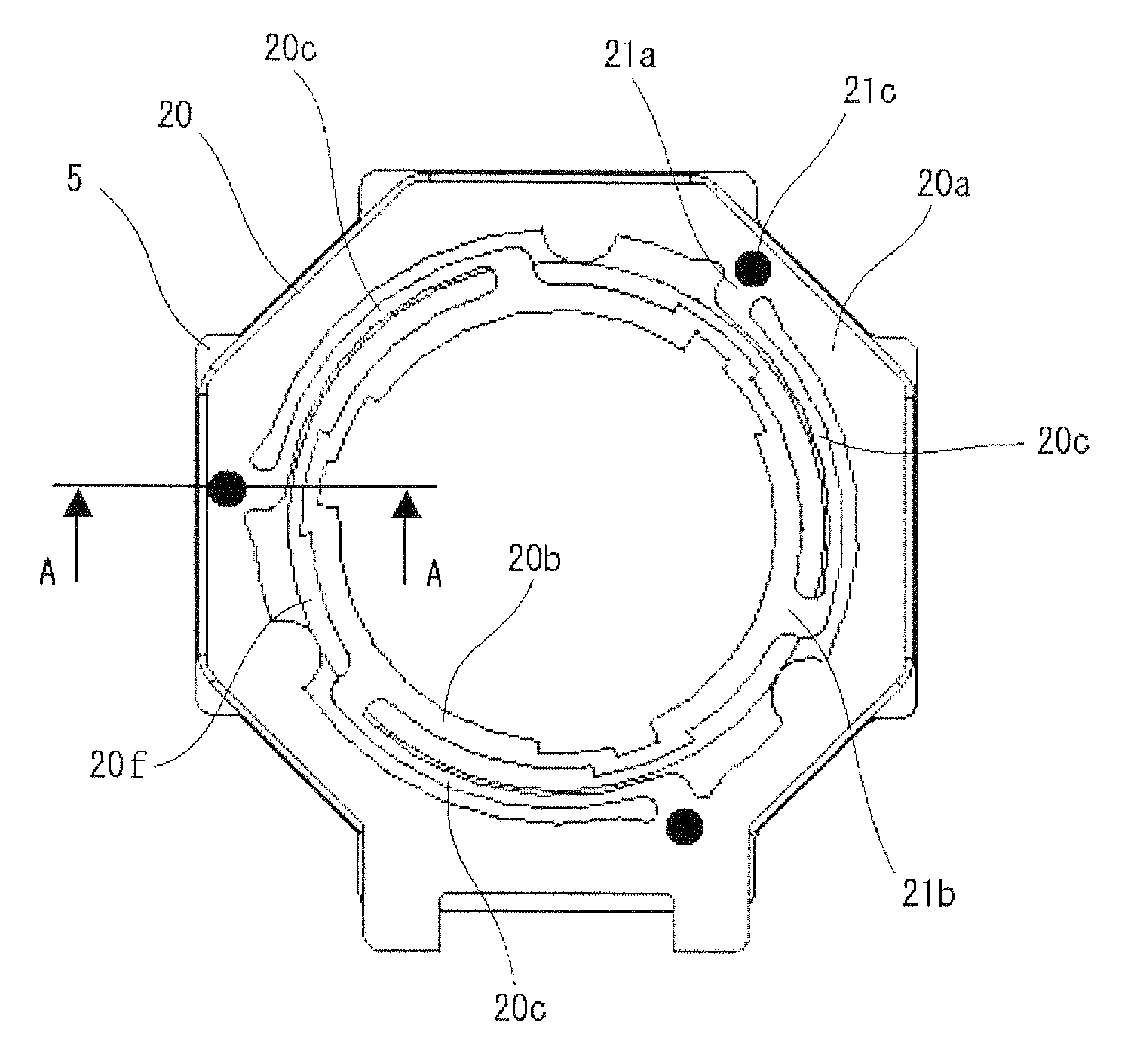
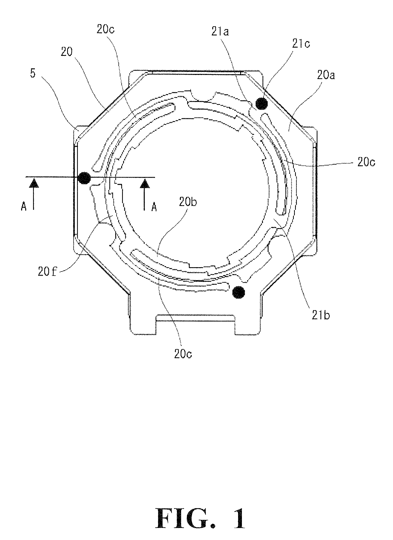
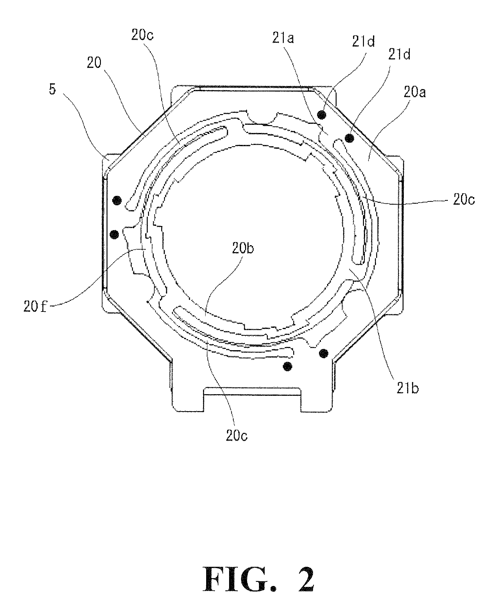
[0050]A camera module is composed from a lens unit (not shown) which constitutes an optical system of the camera module; a holder 8 which houses the lens unit and is displaceable along an optical axis of the lens unit; a coil 7 provided on the holder 8; a yoke 5 which is one of stationary components of the camera module and magnets 6 provided on the yoke 5 for providing a magnetic field to the coil 7; an upper leaf spring 20 and a lower leaf spring 30 for supporting the holder 8; and an imaging element (not shown) provided below the lens unit. In this camera module, the upper leaf spring 20 includes an outer annular portion 21 which is attached to a tope surface of the yoke 5, an inner annular portion 22 provided inside the outer annular portion 21 through an annular spacing 20f and attached to the holder 8, and a plurality of bridge portions 2...


PUM


Abstract

A camera module for small digital cameras and camera-equipped cellular phones includes a lens unit; a holder housing the lens unit and displaceable along an optical axis; a coil on the holder; a yoke and magnets in the yoke providing a magnetic field to the coil; a leaf spring for supporting the holder; and an imaging element below the lens unit. The leaf spring includes an outer annular portion attached to the yoke, an inner annular portion attached to the holder, and bridge portions coupled between the outer and inner annular portion to resiliently support the inner annular portion. Each bridge portion has an outer and an inner annular portion side base part, and extends between an inner peripheral edge of the outer annular portion and an outer peripheral edge of the inner annular portion, the outer annular portion welded to the top surface of the yoke.

Description

BACKGROUND OF THE INVENTION[0001]1. Field of the Invention[0002]This invention relates to a camera module, and more specifically to a camera module that can be used in small-sized electronic apparatuses such as digital cameras, camera-equipped cellular phones and the like.[0003]2. Description of the Prior Art[0004]A camera module having a function of displacing a lens unit in a direction of an optical axis of the lens unit is used in relatively small-sized digital cameras, camera-equipped cellular phones and the like. This function is used for providing an autofocus function and / or zoom function and the like, and is achieved by an interaction between a magnetic field generated by an electrical current flowing in a coil and a magnetic field generated by a yoke and magnets provided on the yoke.[0005]Such a camera module includes a barrel which holds the lens unit, a holder which houses the barrel therein, and a pair of leaf springs for supporting the holder so that the holder is displ...

Claims


Application Information

Patent Timeline
Patent Type & Authority Patents(United States)
IPC IPC(8): H04N5/232G02B7/02G03B13/00H04N5/225
CPCG02B7/08H02K41/0356G03B13/34G02B13/001
Inventor ISHIZAWA, TAKASHIOSAKA, TOMOHIKO
Owner MITSUMI ELECTRIC CO LTD
Why Eureka
Try Eureka