Data processing method, printing apparatus, host apparatus, and printing system

a data processing and host apparatus technology, applied in the field of data processing methods, printing apparatuses, host apparatuses, printing systems, can solve the problems of uneven density, degrade image quality, uneven printing density, etc., and achieve the effect of suppressing uneven printing density, reducing the amount of data transferred from the host apparatus to the printing apparatus, and reducing the amount of data transferred

Inactive Publication Date: 2010-04-27
CANON KK
View PDF11 Cites 20 Cited by
  • Summary
  • Abstract
  • Description
  • Claims
  • Application Information

AI Technical Summary

Benefits of technology

[0031]For example, a data processing method, printing apparatus, host apparatus, and printing system according to the present invention are capable of reducing the data transfer amount from the host apparatus to the printing apparatus, suppressing density unevenness, and reducing the cost of the apparatus.
[0034]The present invention is particularly advantageous since the amount of data transferred from the host apparatus to the printing apparatus can be decreased. In addition, density unevenness is suppressed by executing multi-pass printing so that high-quality image printing can be executed.
[0035]When the data transfer amount can be decreased, the transfer amount per unit time, i.e., the transfer rate can be low. This makes the use of an inexpensive communication interface for low-speed transfer possible, thus reducing the cost.

Problems solved by technology

In such a serial printing apparatus where a plurality of printing elements for dot printing are arrayed in the sub-scanning direction, it has been known that an unevenness in the printing density occurs because of, e.g., errors between the individual printing elements in the manufacture.
This finally causes a density unevenness of a printed image and degrades the image quality, as is known.
This means that a printing failure occurs, resulting in density unevenness.
As a result, the black or white string indicated by b in FIG. 26 is relatively unnoticeable.
Especially, a printing apparatus that must execute high-resolution printing requires a large amount of print data for it, and a high speed print data transfer is necessary.
These factors increase the production cost of the apparatuses.
However, in a case where a memory capacity integrated with a printing apparatus is small, all of mask patterns necessary for multi-pass printing cannot always be stored in the printing apparatus in advance.
However, if a printing apparatus changes a mask pattern for each scan, a total amount of mask patterns is huge.
Therefore, it is not possible to store all of mask patterns into a small capacity memory.

Method used


Image

  • Data processing method, printing apparatus, host apparatus, and printing system
  • Data processing method, printing apparatus, host apparatus, and printing system
  • Data processing method, printing apparatus, host apparatus, and printing system

Examples


first embodiment

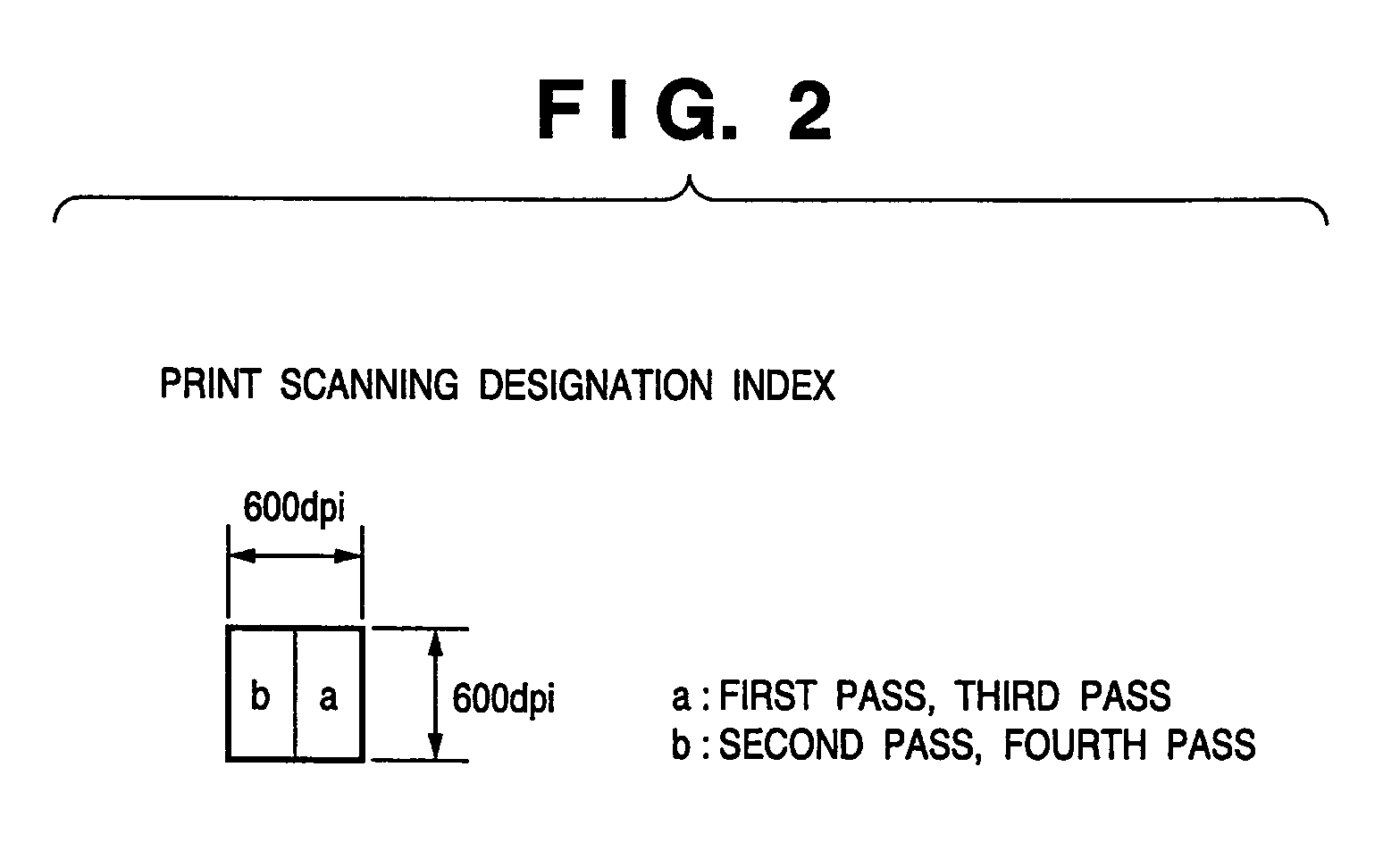
[0083]FIG. 2 is a view showing an index that designates print scanning for quantized data with a resolution of 600×600 dpi, which is obtained by causing the host apparatus to quantize image data of each pixel to three values.

[0084]As shown in FIG. 2, a pixel with the resolution of 600×600 dpi is divided into 2-bit data, i.e., two sub-pixels a and b. The quantized image data are allotted and arranged in a and b. Data arranged in a is printed in odd-numbered passes, i.e., first and third passes. Data arranged in b is printed in even-numbered passes, i.e., second and fourth passes.

[0085]FIG. 3 is a view showing how to allot and arrange quantized image data in accordance with the print scanning designation index shown in FIG. 2.

[0086]For image data quantized to three values, i.e., quantization levels 0, 1, and 2, the number of print dots of quantization level 1 is one, and the number of print dots of quantization level 2 is two.

[0087]The number of print dots of quantization level 0 is z...

second embodiment

[0134]According to the first embodiment as described above, mask pattern information on all of mask patterns to be used in each scan is transferred from the host apparatus to the printing apparatus. For example, information on the mask pattern A itself and information on the mask pattern B itself are transferred in odd-numbered passes which use the mask patterns A and B. However, in this arrangement, the amount of mask pattern data to be transferred is large.

[0135]In this embodiment, in order to reduce the amount of mask pattern data to be transferred, not information on a mask pattern itself but a signal indicating the mask pattern is transferred for part of mask patterns to be used in each scan. In other words, a characteristic feature according to this embodiment is to transfer a signal indicating a particular mask pattern. Note that, since arrangements other than this feature are the same as those in the first embodiment, those arrangements will no longer described.

[0136]FIG. 14...

third embodiment

[0144]In the arrangement to be described in this embodiment, when a sampling mask pattern is transmitted from a printing apparatus to a host apparatus, a printing apparatus holds a sampling mask pattern.

[0145]Image data used in this embodiment is the same as that shown in FIGS. 4, 5A, and 5B described in the first embodiment. Sampling mask patterns are the same as those shown in FIGS. 6A and 6B described in the first embodiment and those shown in FIGS. 11A and 11B. Image data and compressed image data used in each scan printing are the same as those shown in FIGS. 12, 13A, and 13B described in the first embodiment.

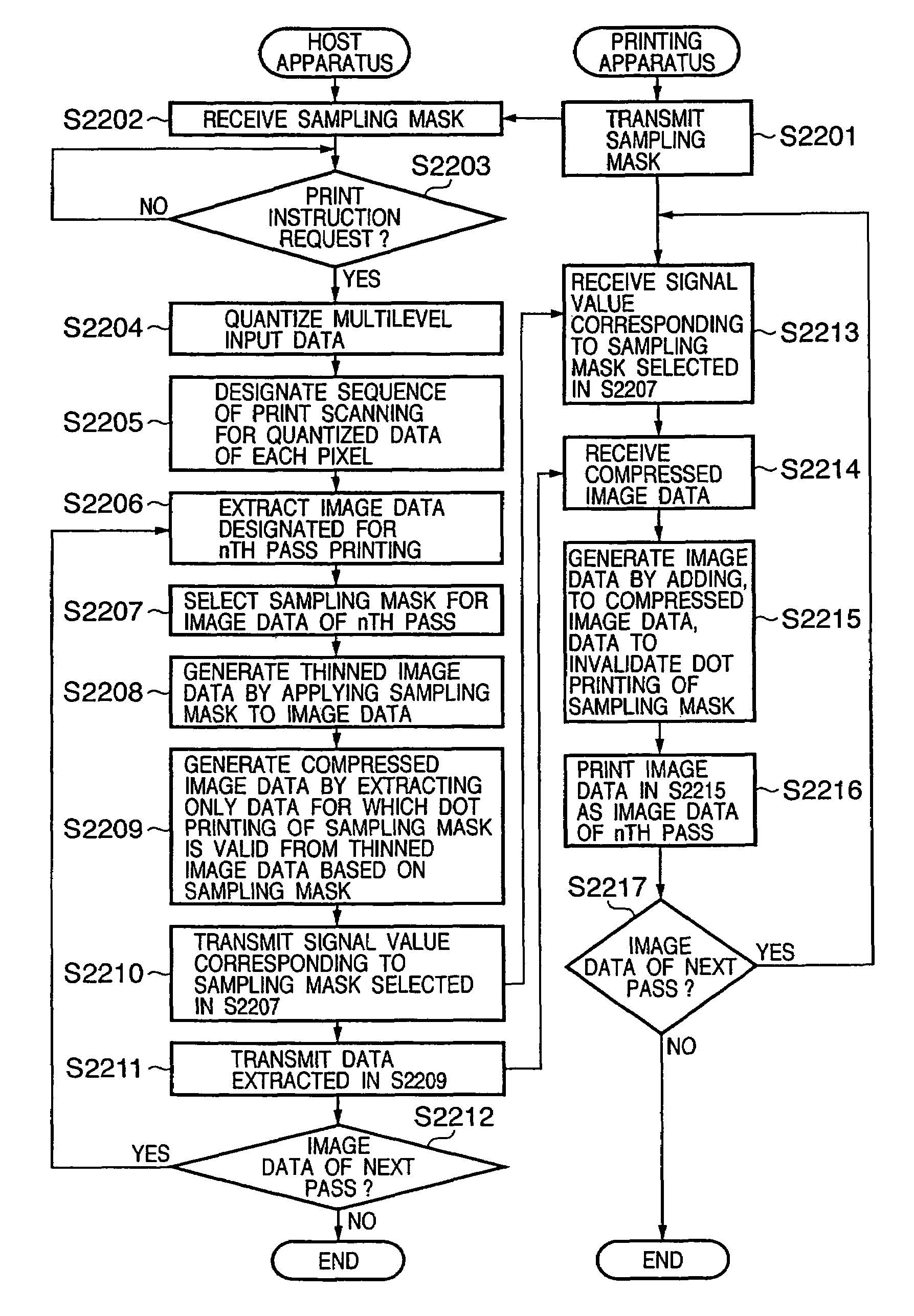
[0146]FIG. 16 is a flowchart showing data processing executed by a printing system according to this embodiment.

[0147]A setup operation will be described first.

[0148]In step S2201, sampling mask patterns to be used for printing are transmitted from a printing apparatus 701 to a host apparatus 700. In step S2202, the host apparatus 700 receives the sampling mask patterns tr...


PUM


Abstract

A data processing method, printing apparatus, host apparatus, and printing system are capable of reducing the data transfer rate from the host apparatus to the printing apparatus, suppressing density unevenness, and reducing the cost of the apparatus.

Description

FIELD OF THE INVENTION[0001]This invention relates to a data processing method, printing apparatus, host apparatus, and printing system and, more particularly, to a printing apparatus which has a printhead and executes printing by discharging ink by, e.g., an inkjet method, a host apparatus connected to the printing apparatus, a printing system including these apparatuses, and a data processing method applicable to the system.BACKGROUND OF THE INVENTION[0002]Conventionally, serial printing apparatuses which execute printing by using various printing methods in accordance with print data transferred from a host apparatus are widely used. Especially a printing apparatus employing a dot matrix method forms a desired printed image on a sheet-like printing medium by alternately repeating an operation of moving a carriage with a printhead capable of dot printing and an operation of conveying the printing medium in a direction perpendicular to the carriage moving direction. The carriage mo...

Claims


Application Information

Patent Timeline
Patent Type & Authority Patents(United States)
IPC IPC(8): H04N1/60H04M1/40H04N1/46
CPCG06F3/1212G06F3/1219G06F3/1284G06F3/1245G06F3/122
Inventor KANDA, HIDEHIKOKAWATOKO, NORIHIROCHIKUMA, TOSHIYUKIMORIYAMA, JIROHAMASAKI, YUJISAKAMOTO, ATSUSHIHAYASHI, AYA
Owner CANON KK
Why Eureka
Try Eureka