Selectably elevatable injector for coiled tubing

a coiled tubing and injector technology, applied in the direction of drilling casings, drilling pipes, borehole/well accessories, etc., can solve the problems of tubing often becoming stuck in the hole, increasing the uplift force, and requiring considerable setup and rig downtime, etc., to achieve the effect of increasing the vertical tension

Inactive Publication Date: 2010-05-04
TOM C GIPSON
View PDF4 Cites 28 Cited by
  • Summary
  • Abstract
  • Description
  • Claims
  • Application Information

AI Technical Summary

Benefits of technology

[0009]This invention pertains to a selectably elevatable tubing injector for a mobile self-contained unitized coil tubing rig for the drilling and workover of petroleum wells. In particular, the present invention concerns a mechanism for positioning a trailer mounted coiled tubing injector either in a first stowed position on the deck of the transport trail

Problems solved by technology

When being transported, such a conventional injector must be restrained by tiedown means, so the conventional approach involves considerable setup and rig down time, as well as necessitating lifting equipment.
Furthermore, whenever a coiled tubing string is used to drill we

Method used


Image

  • Selectably elevatable injector for coiled tubing
  • Selectably elevatable injector for coiled tubing
  • Selectably elevatable injector for coiled tubing

Examples


Embodiment Construction

[0030]As a note, the use of the terms “invention”, “present invention” and variations thereof throughout the subject patent application (and headings therein) are intended to refer or relate to one or more embodiments of the present application, not necessarily every embodiment or claim of the application.

[0031]Referring now to the drawings, it is noted that like reference characters designate like or similar parts throughout the drawings. The figures, or drawings, are not intended to be to scale. For example, purely for the sake of greater clarity in the drawings, wall thicknesses and spacings are not dimensioned as they actually exist in the assembled embodiments.

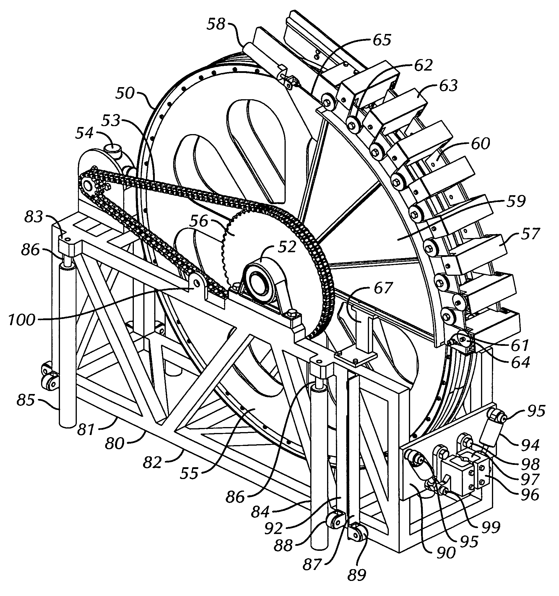
[0032]The structural components of the selectably elevatable coiled tubing injector are normally constructed of steel. For some purposes involving contact between the tubing and the tensioning wheel, high stiffness rubber or plastics are typically used.

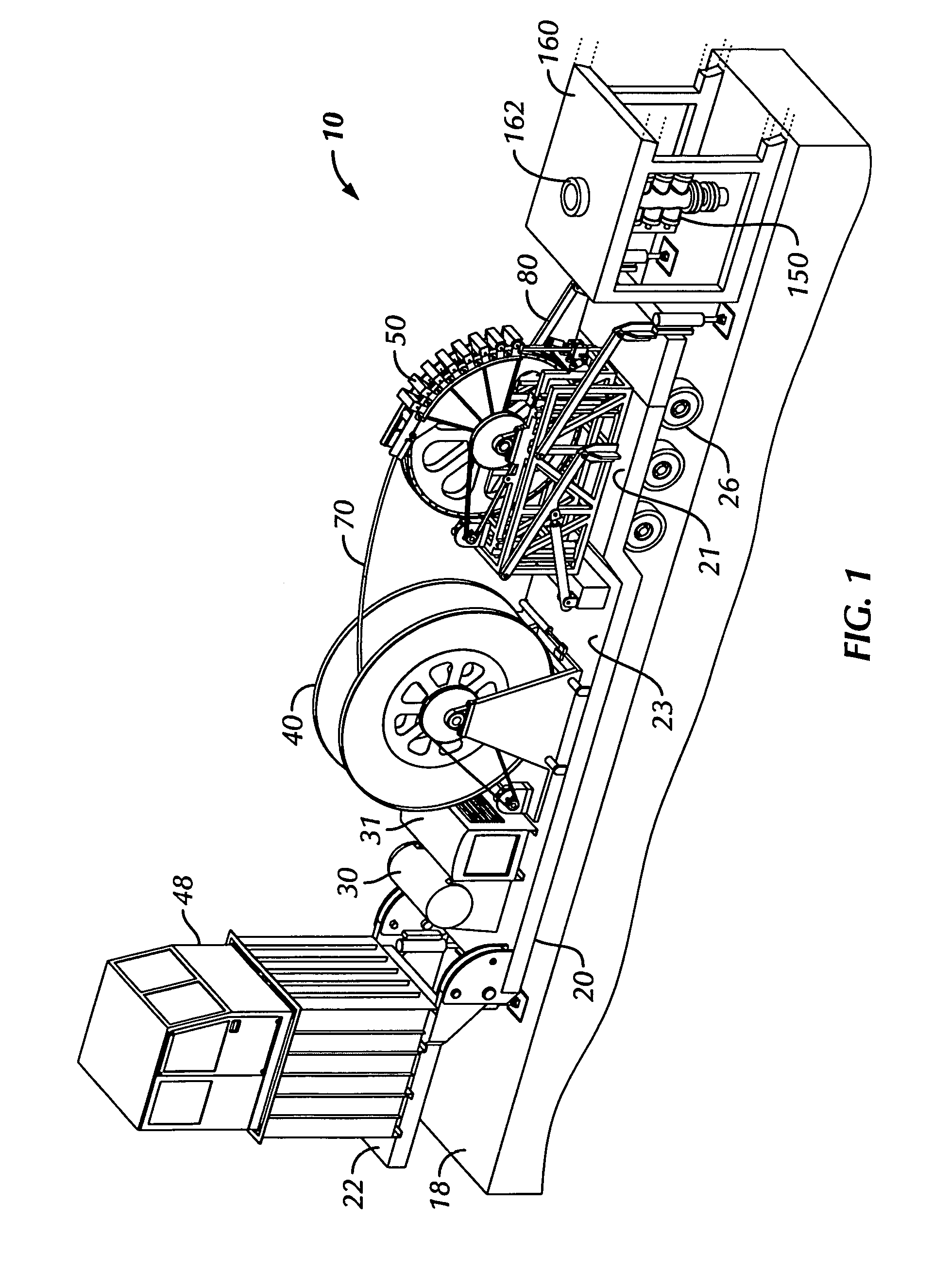
[0033]Much of the equipment mounted on the trailer in FIG. 1 is commer...


PUM


Abstract

A selectably elevatable coiled tubing injector is described that is suitable for a mobile self-contained unitized coil tubing rig for the drilling and workover of petroleum wells. The selectably elevatable coiled tubing injector includes a mechanism for positioning a trailer mounted coiled tubing injector either in a first stowed position on the deck of the transport trailer or in a second position resting on an elevated rig floor of a drilling rig. Furthermore, the selectably elevatable coiled tubing injector includes a further mechanism for selectably elevating the injector above its second position on the rig floor while clamping the tubing in order to provide additional tension on the tubing string or to raise the tubing deployed within a well.

Description

BACKGROUND OF THE INVENTION[0001]1. Field of the Invention[0002]The present invention relates to a selectably elevatable coiled tubing injector for a mobile self-contained unitized coil tubing rig for the drilling and workover of petroleum wells. In particular, the present invention concerns a mechanism for positioning a trailer mounted coiled tubing injector either in a first stowed position on the deck of the transport trailer or in a second position resting on an elevated rig floor of a drilling rig.[0003]2. Description of the Related Art[0004]Coiled tubing rigs primarily include a tubing storage reel and a coiled tubing injector for forcing a string of coiled tubing into or pulling it out of a well. Coiled tubing rigs are commonly used in the oilfield for reasons of speed and low cost operation. Due to advances in the ability to run downhole drilling motors on the lower end of a coiled tubing drill string, a need has arisen for coiled tubing injectors which can be positioned on ...

Claims


Application Information

Patent Timeline
IPC IPC(8): E21B19/22
CPCE21B19/22
Inventor GIPSON, TOMMIE CARROLL
Owner TOM C GIPSON
Why Eureka
Try Eureka