Image forming apparatus

a technology of forming apparatus and image, which is applied in the direction of printing, other printing apparatus, etc., can solve the problems of deteriorating image quality, major quality inconvenience, and incomplete transfer to the recording medium, etc., and achieve the effect of reducing the deterioration of image quality

Inactive Publication Date: 2010-05-04
FUJIFILM CORP
View PDF6 Cites 39 Cited by
  • Summary
  • Abstract
  • Description
  • Claims
  • Application Information

AI Technical Summary

Benefits of technology

[0011]The present invention is contrived in view of the foregoing circumstances, an object thereof being to provide an image forming apparatus which is able to prevent deterioration of image quality in an image formed on a recording medium, such as paper, even if transfer errors arise.
[0014]According to this aspect of the present invention, the state of the transfer surface after the transfer from the intermediate transfer body is determined by means of the transfer state determination device, and the image data is corrected by the image correction device on the basis of the determined state of the transfer surface. Accordingly, it is possible to prevent deterioration in the quality of the image formed on the recording medium.
[0021]According to this aspect of the present invention, the determination accuracy of the transfer state is improved.
[0024]According to the present invention, it is possible to reduce the deterioration of the quality of an image formed on a recording medium, such as paper, even if a transfer error occurs.

Problems solved by technology

However, there is a possibility that a portion of the coloring material remains on the intermediate transfer body, and the transfer to the recording medium, such as paper, from the intermediate transfer body, is not complete.
If transfer to the recording medium is insufficient due to deterioration of the transfer surface in this way, then density non-uniformities occur (more specifically, regions of weak density occur) in the printed object, and it can lead to major quality inconvenience.
The technology described in Japanese Patent Application Publication No. 2001-347747 increases the viscosity of liquid droplets and transfers them to a recording medium; however, it cannot deal with the issue of degradation of the transfer surface, and if transfer errors arise due to degradation of the transfer surface, then print quality can decline.
The technology described in Japanese Patent Application Publication No. 2001-10224 performs cleaning of the transfer surface; however, if the transfer surface is degraded permanently due to the formation of scratches, or the like, then transfer errors can arise and print quality can decline.

Method used


Image

  • Image forming apparatus
  • Image forming apparatus
  • Image forming apparatus

Examples


first embodiment

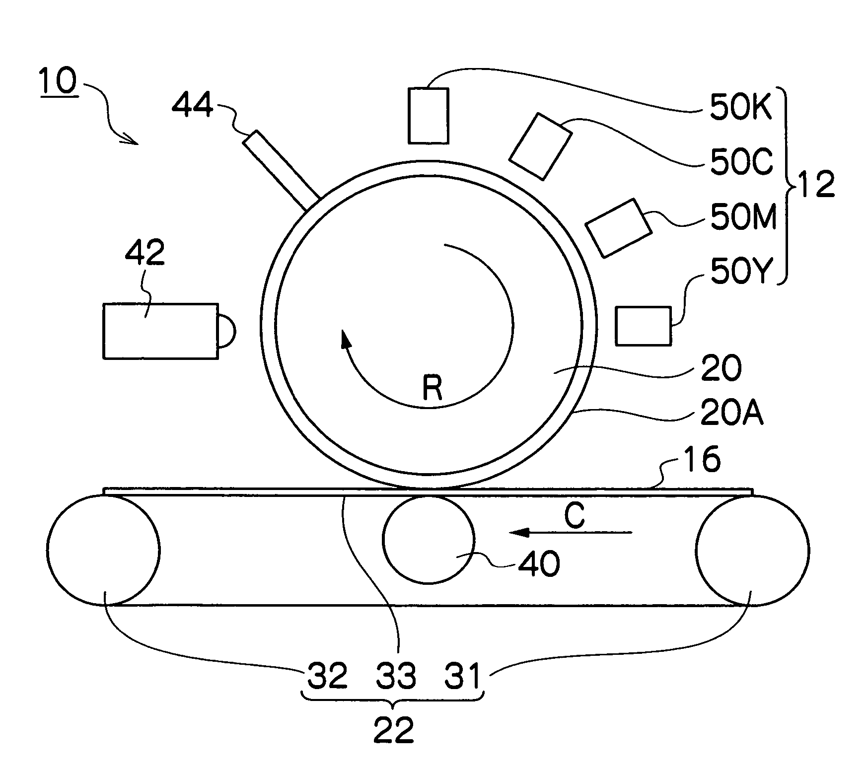
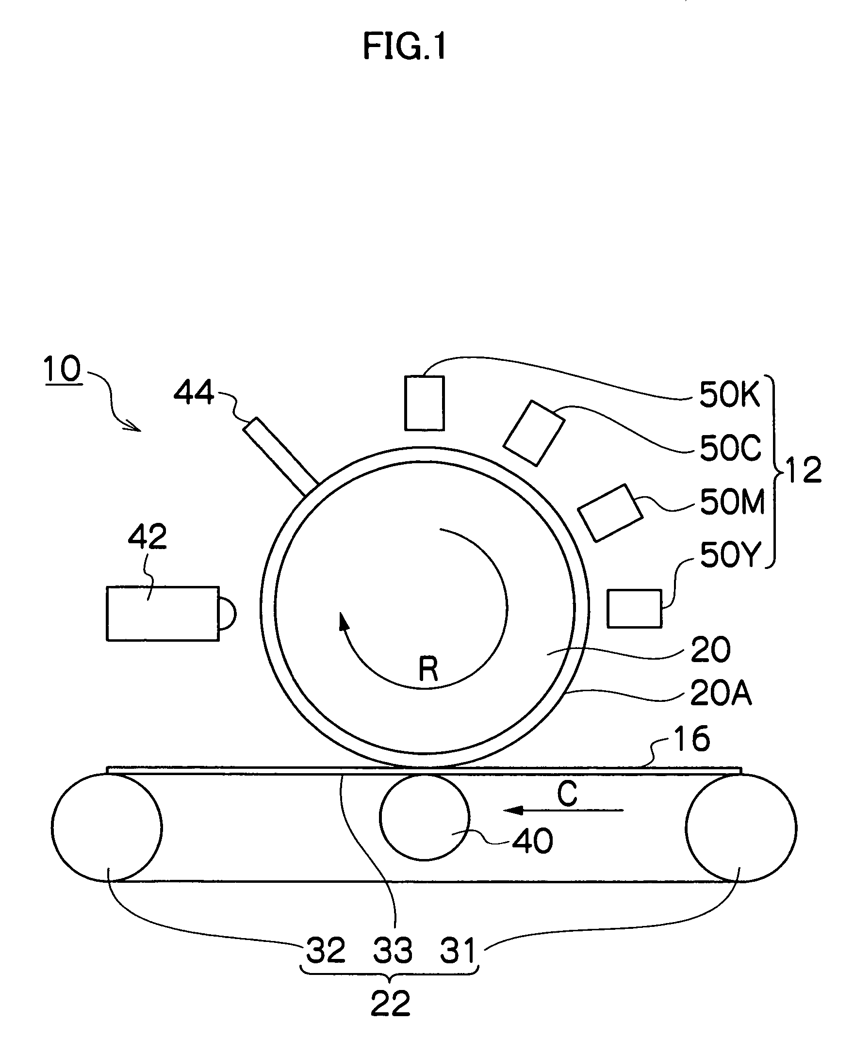
[0044]FIG. 1 is a general schematic drawing showing the general functional composition of an image forming apparatus 10 relating to the present invention.

[0045]In FIG. 1, the image forming apparatus 10 according to the present embodiment comprises: a liquid droplet ejection unit 12 (image forming device) which ejects liquid droplets (ink droplets) containing coloring material on the basis of image data input from a source external to the image forming apparatus 10; a transfer drum 20 (intermediate transfer body) having a transfer surface 20A on which the liquid droplets ejected from the liquid droplet ejection unit 12 are deposited; a conveyance unit 22 which conveys recording paper 16 onto which the image (transfer image) formed on the transfer surface 20A of the transfer drum 20 is transferred; a pressing roller 40 which presses the recording paper 16 against the transfer surface 20A of the transfer drum 20; a transfer state determination unit 42 which determines the state of the ...


PUM


Abstract

The image forming apparatus comprises: an image forming device which includes an intermediate transfer body having a transfer surface on which an image is formed according to a first image data, the image forming device performing a transfer of the image onto a recording medium from the transfer surface; a transfer state determination device which determines a state of the transfer surface after the transfer of the image onto the recording medium has been performed; and an image correction device which corrects a second image data corresponding to an image formed on the transfer surface, according to the state of the transfer surface determined by the transfer state determination device.

Description

BACKGROUND OF THE INVENTION[0001]1. Field of the Invention[0002]The present invention relates to an image forming apparatus, and more particularly, to an image forming apparatus which forms an image on an intermediate transfer body by depositing liquid on the intermediate transfer body, and then transfers the image onto a recording medium such as paper.[0003]2. Description of the Related Art[0004]An image forming apparatus is known in which an image is formed on an intermediate transfer body by depositing ink onto the intermediate transfer body, and the image on the intermediate transfer body is then transferred onto a recording medium such as paper.[0005]Japanese Patent Application Publication No. 2001-347747 discloses technology in which, firstly, a material which increases the viscosity of liquid droplets by making contact with the liquid droplets is deposited on the intermediate transfer body, whereupon liquid droplets are placed in contact with the material in accordance with a...

Claims


Application Information

Patent Timeline
Patent Type & Authority Patents(United States)
IPC IPC(8): B41J29/38B41J2/205B41J29/393
CPCB41J2/0057B41J2/04508B41J2/04558B41J2/04586B41J2/0451B41J2002/14459
Inventor YAMANOBE, JUN
Owner FUJIFILM CORP
Why Eureka
Try Eureka