Stretch resistant embolic coil delivery system with combined mechanical and pressure release mechanism

a coil delivery and strain-resistant technology, applied in the field of catheter-based deployment systems, can solve the problems of inability to develop the necessary pressure to release the embolic device, inability to secure the fluid seal between the catheter and the embolic device, and inability to meet the needs of the embolic device,

Active Publication Date: 2010-05-04
CODMAN & SHURTLEFF INC
View PDF67 Cites 96 Cited by
  • Summary
  • Abstract
  • Description
  • Claims
  • Application Information

AI Technical Summary

Problems solved by technology

Dimensional variations inherent in the manufacturing process create the risk that the fit between the catheter and the embolic device will be too tight or too loose or comprise an incomplete fluid seal.
If the catheter holds the embolic device too tightly, it may require more fluid pressure to release the embolic device, which pressure may not be attainable by the syringe or which pressure may endanger the body vessel.
If an incomplete fluid seal is formed between the catheter or sleeve and the associated embolic device, it may be very difficult or even impossible to develop the necessary pressure to release the embolic device.
Even if possible, developing the necessary pressure may take longer than expected, thereby increasing the time required to deploy the embolic device.
With the present approach, it has been determined that characteristics such as these may be less than desirable.

Method used


Image

  • Stretch resistant embolic coil delivery system with combined mechanical and pressure release mechanism
  • Stretch resistant embolic coil delivery system with combined mechanical and pressure release mechanism
  • Stretch resistant embolic coil delivery system with combined mechanical and pressure release mechanism

Examples


Embodiment Construction

[0047]As required, detailed embodiments of the present invention are disclosed herein; however, it is to be understood that the disclosed embodiments are merely exemplary of the invention, which may be embodied in various forms. Therefore, specific details disclosed herein are not to be interpreted as limiting, but merely as a basis for the claims and as a representative basis for teaching one skilled in the art to variously employ the present invention in virtually any appropriate manner.

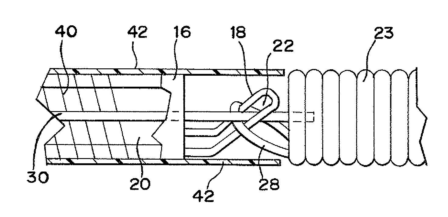
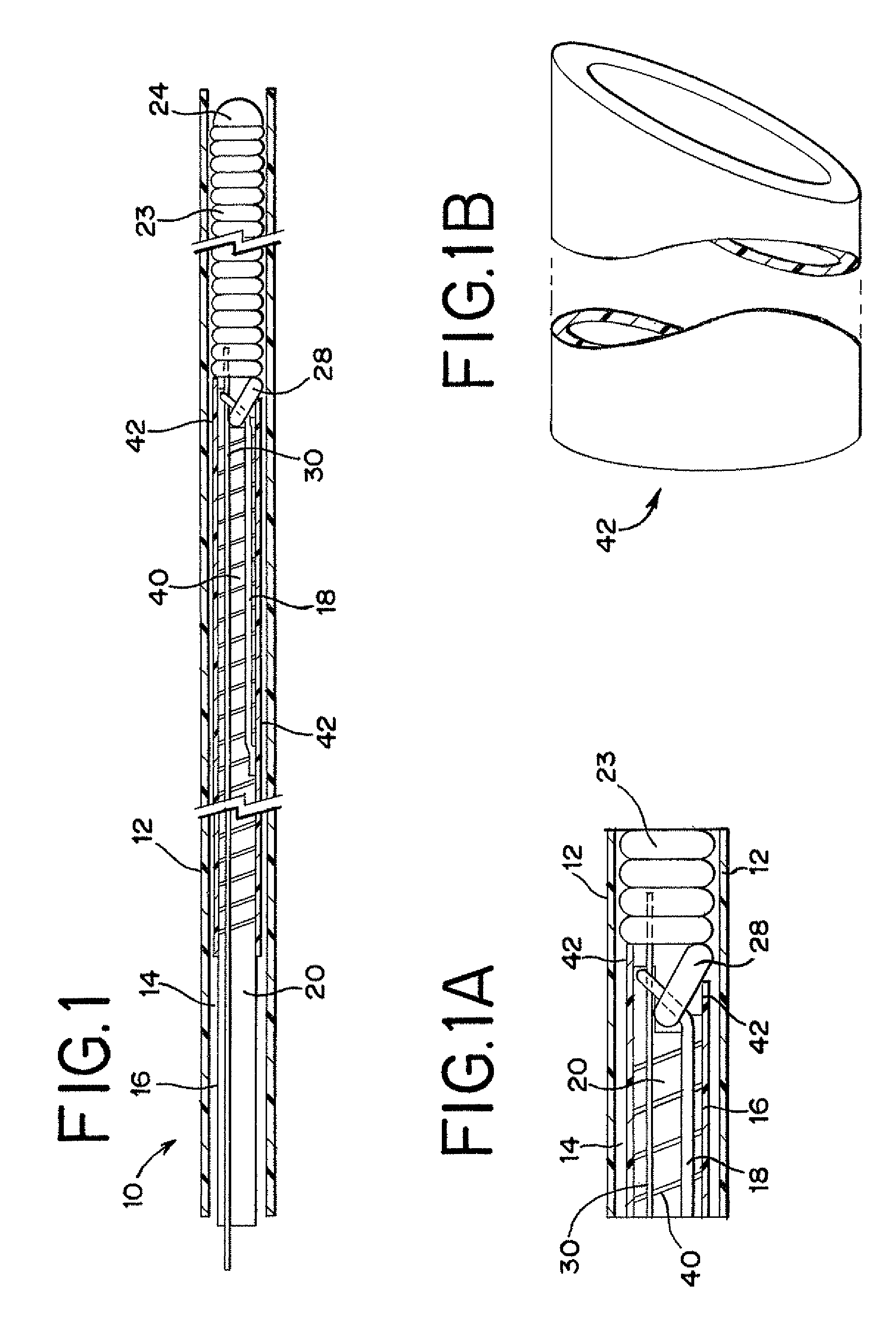
[0048]FIGS. 1 and 1A generally illustrate one embodiment of a vascular occlusive embolic device deployment system 10 which includes a sheath introducer 12 having a lumen 14 extending therethrough and having an elongated pusher member 16 slidably disposed within the lumen 14 of the sheath introducer 12. An engagement member 18 extends from the pusher member 16 and has an aperture (to be described hereinafter) extending through the distal end thereof. The engagement member 18 may be formed from a dis...


PUM


Abstract

A medical device for placing an embolic device at a predetermined site within a vessel of the body including a delivery catheter and a flexible pusher member slidably disposed within the lumen of the catheter. A fluid pressure source is coupled to the proximal end of the pusher member. An embolic device is retained at the distal end of the pusher member by a mechanical interlocking mechanism. The distal end of the pusher member includes a spiral ribbon section encircled by a tubular member. The tubular member or the distal end of the pusher member directs fluid from the fluid pressure source against the embolic device. The mechanical interlocking mechanism is disengaged from the embolic device and a fluid pressure is applied against the embolic device to ensure the release of the embolic device.

Description

CROSS-REFERENCE TO RELATED APPLICATION(S)[0001]This patent application is a continuation-in-part of U.S. patent application Ser. No. 11 / 301,865, filed on Dec. 12, 2005, entitled, “Stretch Resistant Embolic Coil Delivery System With Mechanical Release Mechanism,” which is a continuation-in-part of U.S. patent application Ser. No. 11 / 143,052, filed on Jun. 2, 2005, entitled, “Stretch Resistant Embolic Coil Delivery System With Mechanical Release Mechanism.”BACKGROUND OF THE INVENTION[0002]1. Field of the Invention[0003]The present invention relates to a medical device for placing a stretch resistant embolic device at a predetermined site within a vessel of the human body, and more particularly, relates to a catheter-based deployment system for delivering an embolic device. This device is particularly suited to transport an embolic device, such as a stretch resistant embolic coil, through the tortuous vasculature of the human brain to a selected site within the vessel or within an aneu...

Claims


Application Information

Patent Timeline
Patent Type & Authority Patents(United States)
IPC IPC(8): A61M29/00A61F2/06
CPCA61B17/12022A61B17/12113A61B17/12154A61B2017/12054A61B2017/00477
Inventor DAVIS, III, RICHARD CHAMPIONTHINNES, JR., JOHN H.
Owner CODMAN & SHURTLEFF INC
Why Eureka
Try Eureka