
Method of controlling a driver assistance system and an associated apparatus

a technology of driver assistance and associated equipment, which is applied in the direction of burglar alarm mechanical actuation, instruments, transportation and packaging, etc., can solve the problems of completely deactivating the driver assistance system, unable to output a warning signal in a real danger situation, and unable to control the driver assistance system

Active Publication Date: 2010-05-04
APTIV TECH LTD
View PDF14 Cites 9 Cited by
  • Summary
  • Abstract
  • Description
  • Claims
  • Application Information

AI Technical Summary

Benefits of technology

The present invention provides a method and apparatus for controlling a driver assistance system that can better distinguish critical danger situations from non-dangerous risk situations. The system uses an activity state of the driver to determine if a warning signal should be output. By measuring the driver's activity state, the system can better determine if the driver is paying attention or not. This allows for a more effective use of the driver assistance system as it only outputs a warning signal when necessary. The method and apparatus use an additional control module that determines the driver's activity state based on input values from the vehicle. This additional control module can also suppress the outputting of a warning signal if the driver is not paying attention. The method and apparatus can also adapt the threshold values for identifying a danger situation based on the type of danger situation and the driver's behavior. This allows for a more accurate and effective driver assistance system.

Problems solved by technology

It is a disadvantage of these driver assistance systems that the pre-set limit values do not lead to a satisfactory result for every driver and for every style of driving.
In this case, a warning by the driver assistance system is not wanted by the driver and, contrary to the original intention, the output warning signal can even result in a dangerous incorrect reaction of the driver.
The described insufficiencies of conventional driver assistance systems have the result that many drivers as a rule completely deactivate the driver assistance system.
The driver assistance system can thereby naturally also no longer output a warning signal in a real danger situation.

Method used


Image

  • Method of controlling a driver assistance system and an associated apparatus
  • Method of controlling a driver assistance system and an associated apparatus
  • Method of controlling a driver assistance system and an associated apparatus

Examples


Embodiment Construction

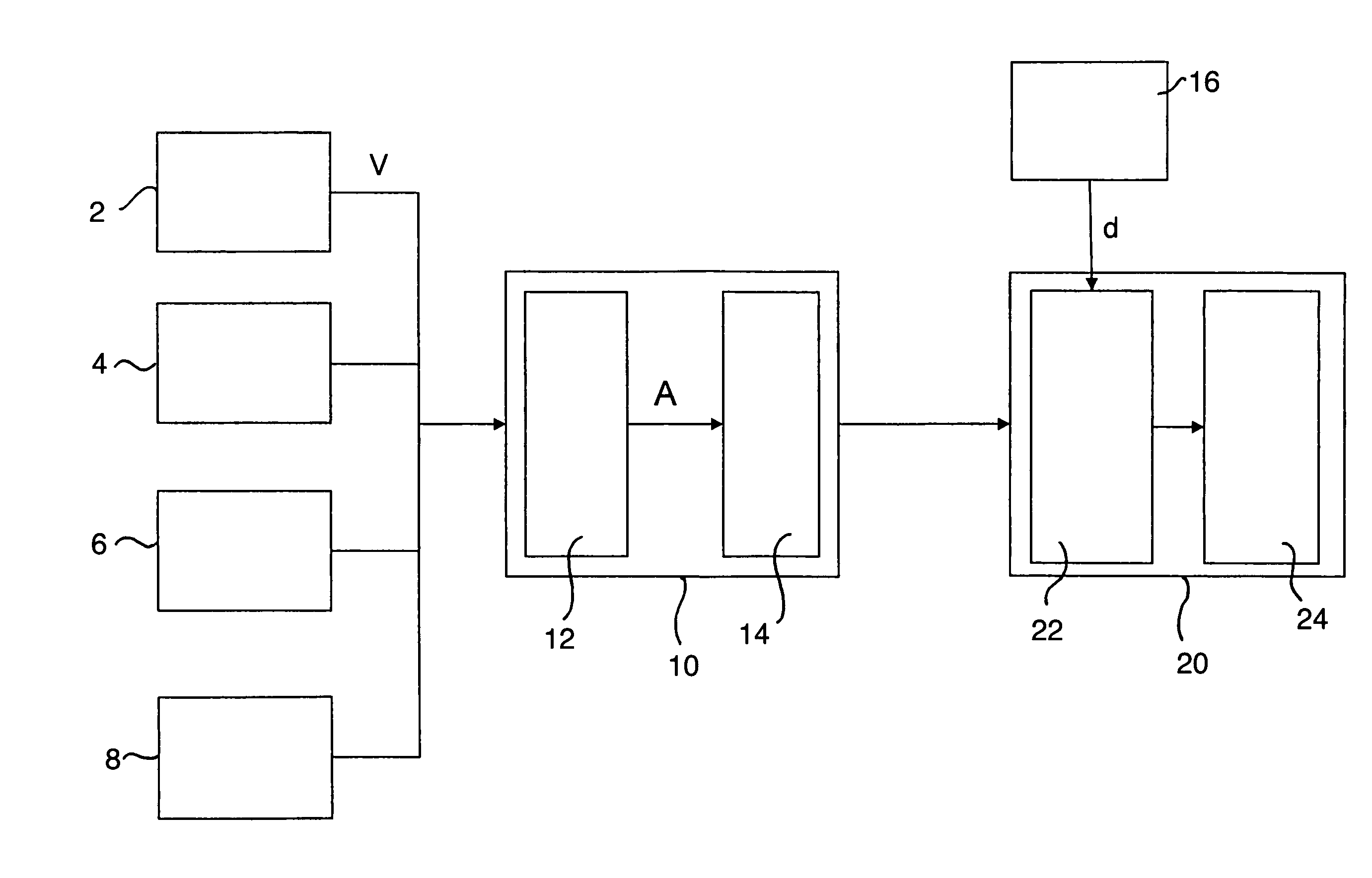
[0027]The apparatus in accordance with the invention, which is built into a motor vehicle, is shown schematically in FIG. 1 and includes a control module 10 and a driver assistance system 20. Different measuring devices 2, 4, 6, 8 belonging to the vehicle are shown schematically at the left in FIG. 1 and are connected to the control module 10 to transmit signals thereto. A speed v is forwarded to the control module from a speedometer 2 and a sensor 4 measures the pressure exerted onto a brake pedal or the pedal position of the brake pedal and forwards a corresponding measured value to the control module 10. A steering angle sensor 6 measures the angular position of the steering wheel and forwards it to the control module 10 as the input value. Finally, a sensor 8 monitors the actuation of the indicator and, when the indicator is actuated, forwards a corresponding input signal to the control module 10. In addition to the four input values listed, other input values can naturally also...


PUM


Abstract

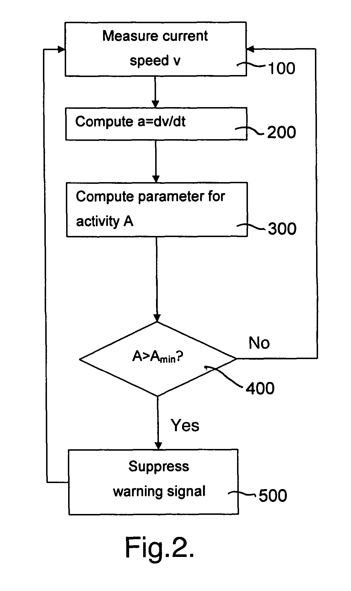
The present invention relates to a method of controlling a driver assistance system which can identify a danger situation with reference to a comparison of measured data with predetermined limit values and which can output a warning signal when it has identified a danger situation of this type. An additional control module is provided which determines an activity state of the driver in dependence on at least one input value which permits a conclusion on actions carried out by a driver and can suppress the outputting of the warning signal in dependence on this activity state.

Description

TECHNICAL FIELD[0001]The present invention relates to a method of controlling a driver assistance system which can identify a danger situation with reference to a comparison of measured data with predetermined limit values and which can output a warning signal when it has identified a danger situation of this type.[0002]The present invention also relates to an apparatus for carrying out a method of this type which includes a driver assistance system with a signal output device and an additional control module connected to the driver assistance system.BACKGROUND OF THE INVENTION[0003]Driver assistance systems and associated control methods and apparatus for the carrying out of methods of this type are known from the prior art. Driver assistance systems exist, for example, which measure the distance to a preceding vehicle or to an obstacle and compare this distance with a stored minimum distance. If the stored minimum distance is fallen below, a warning signal is output by the driver ...

Claims


Application Information

Patent Timeline
Patent Type & Authority Patents(United States)
IPC IPC(8): B60Q1/00
CPCG08B21/06
Inventor PARK, SU-BIRM
Owner APTIV TECH LTD
Learn More