
Detection system, method for detecting objects and computer program therefor

a detection system and object technology, applied in the field of detection system and to a detection method and a computer program for objects, can solve problems such as the inability to detect objects satisfactorily

Inactive Publication Date: 2010-05-04
NEDERLANDSE ORG VOOR TOEGEPAST NATUURWETENSCHAPPELIJK ONDERZOEK TNO
View PDF16 Cites 4 Cited by
  • Summary
  • Abstract
  • Description
  • Claims
  • Application Information

AI Technical Summary

Benefits of technology

The invention provides a detection system that reduces false signaling of objects by comparing and testing objects detected based on two signals. The system can detect objects based on features provided by both the camera and radar, resulting in more accurate object description. The invention also includes a method for reliable detection of objects, a computer program for detecting objects, and a detection system for vehicles that can predict potential collisions with objects. The detection system is more accurate than existing devices, reducing false signals and improving reliability.

Problems solved by technology

A drawback of this known method is that the detection of objects does not work satisfactorily, because it involves a high chance of false alarm.

Method used


Image

  • Detection system, method for detecting objects and computer program therefor
  • Detection system, method for detecting objects and computer program therefor
  • Detection system, method for detecting objects and computer program therefor

Examples


Embodiment Construction

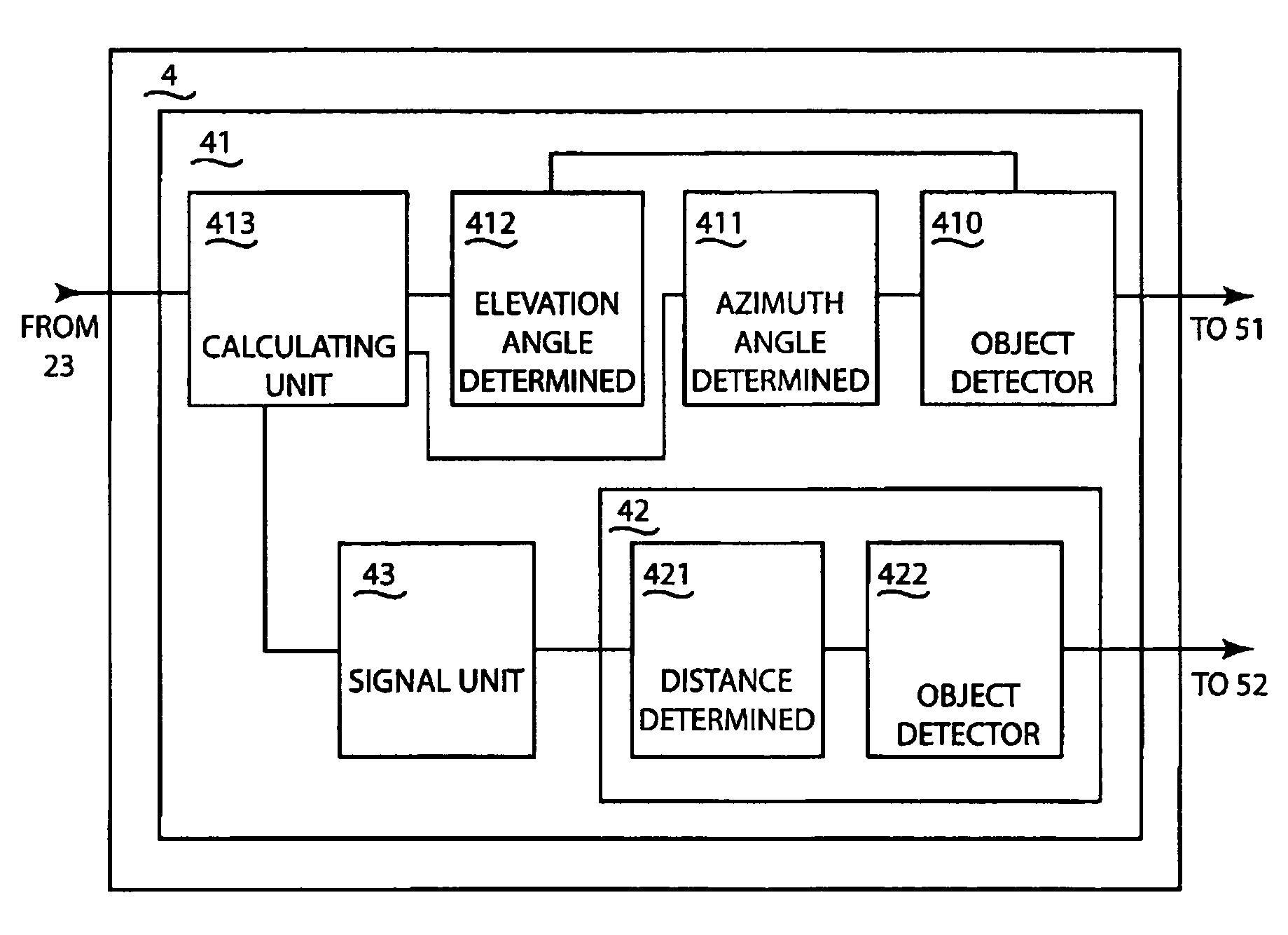
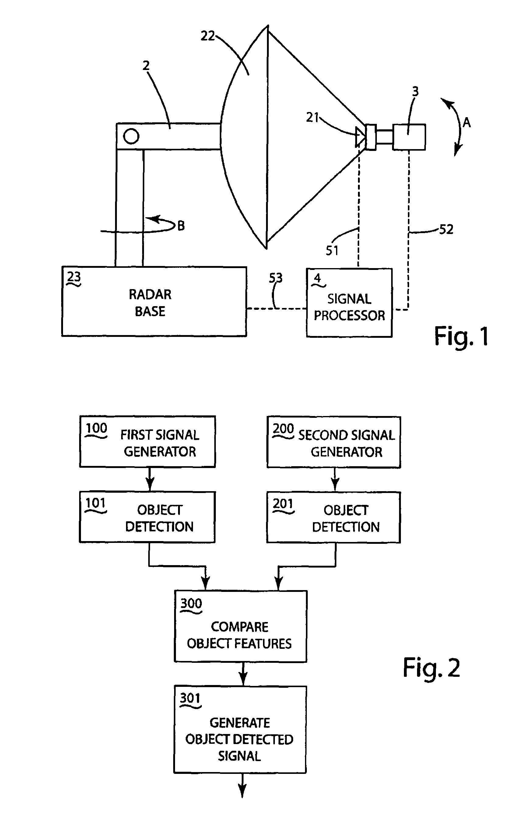
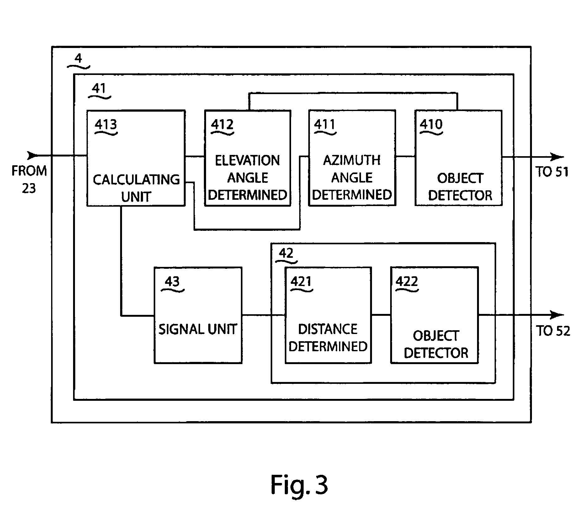
[0017]FIG. 1 schematically shows an example of an embodiment of a detection system according to the invention. The detection system 1 comprises a radar device 2 and an optical sensor, in the example shown a camera 3. The radar device 2 and camera 3 are communicatively connected with a signal processor 4, as is indicated in the Figure by the broken lines 51 and 52. Via the communicative connection 52, the camera 3 can send to the signal processor 4 a first signal which represents a camera measurement performed by the camera. Via the communicative connection 51, the radar device 2 can send to the signal processor 4 a second signal which represents a radar measurement performed by the radar.

[0018]The example of a detection system 1 in FIG. 1 is suitable for carrying out a method for detecting objects according to the invention. An example of a method according to the invention is shown in FIG. 2. In step 100, a first signal is generated, which represents an optical measurement, such as...


PUM


Abstract

A detection system (1) having an optical sensor (3), a radar device (2) and a signal processor (4) communicatively connected with the optical sensor and the radar device. The signal processor comprises: a first detector (41, 410-413) for detecting a first object on the basis of a first signal coming from the optical sensor and determining at least one first property of the first object; a second detector (42, 420-421) for detecting a second object on the basis of a second signal coming from the radar device and determining at least one second property of that second object, and a signaling unit (43) for producing a signal if the at least one first property and the at least one second property satisfy a predetermined condition. Further, a method for detecting objects, comprising: generating (100) a sensor signal with an optical sensor; detecting (101) a first object on the basis of the sensor signal; generating (200) a radar signal; detecting (201) a second object on the basis of the radar signal; producing (300) a detection signal if both on the basis of the sensor signal and on the basis of the radar signal the same object is detected. Also, a computer program with program code for performing one or more steps of such a method.

Description

CROSS REFERENCE TO RELATED APPLICATIONS[0001]This application claims priority of Netherlands Patent Application No. 1,023,016 dated Mar. 25, 2003.BACKGROUND OF THE INVENTION[0002]This invention relates to a detection system and to a method and a computer program for detecting objects.[0003]American patent publication U.S. Pat. No. 6,061,014 discloses a surveillance method for wide areas. According to this method, a thermal camera and a radar device are utilized, which scan an area. Movements in the area are detected by the radar device, while objects differing from the environment in temperature, such as people, are detected with the camera. In one embodiment, after detection of an object with the radar device, the object is identified with the thermal camera and subsequently an alarm can be generated, for instance if the object is a moose or a wolf.[0004]A drawback of this known method is that the detection of objects does not work satisfactorily, because it involves a high chance ...

Claims


Application Information

Patent Timeline
Patent Type & Authority Patents(United States)
IPC IPC(8): G01S13/86G01S13/72
CPCG01S13/867G01S13/86G01S13/723
Inventor HUIZING, ALBERT GEZINUSKESTER, LEONARDUS JOHANNES HUBERTUS MARIATHEIL, ARNE
Owner NEDERLANDSE ORG VOOR TOEGEPAST NATUURWETENSCHAPPELIJK ONDERZOEK TNO
Learn More