Crossfire tube assembly for gas turbines

a technology of crossfire tube and gas turbine, which is applied in the direction of machines/engines, mechanical equipment, lighting and heating apparatus, etc., can solve the problems of hot gases escaping, crossfire tube damage to adjacent parts of the turbine, and the sealing capability of prior crossfire tube assemblies of this type has been brought into question

Active Publication Date: 2010-05-11
GE INFRASTRUCTURE TECH INT LLC
View PDF10 Cites 10 Cited by
  • Summary
  • Abstract
  • Description
  • Claims
  • Application Information

AI Technical Summary

Problems solved by technology

While those bellows assemblies have performed and have demonstrated significant improvement over prior crossfire tube assemblies, the sealing capability of prior crossfire tube assemblies of this type has been brought into question.
Absent an air tight seal, hot gases escaping from the crossfire tubes may damage adjacent parts of the turbine.

Method used


Image

  • Crossfire tube assembly for gas turbines
  • Crossfire tube assembly for gas turbines
  • Crossfire tube assembly for gas turbines

Examples


Embodiment Construction

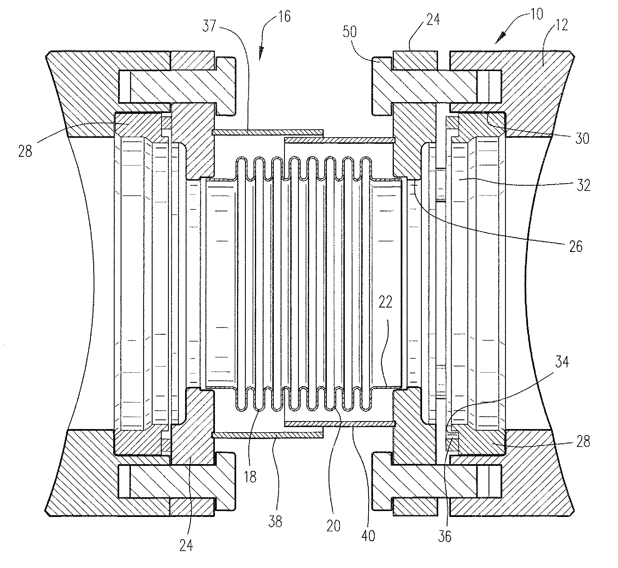
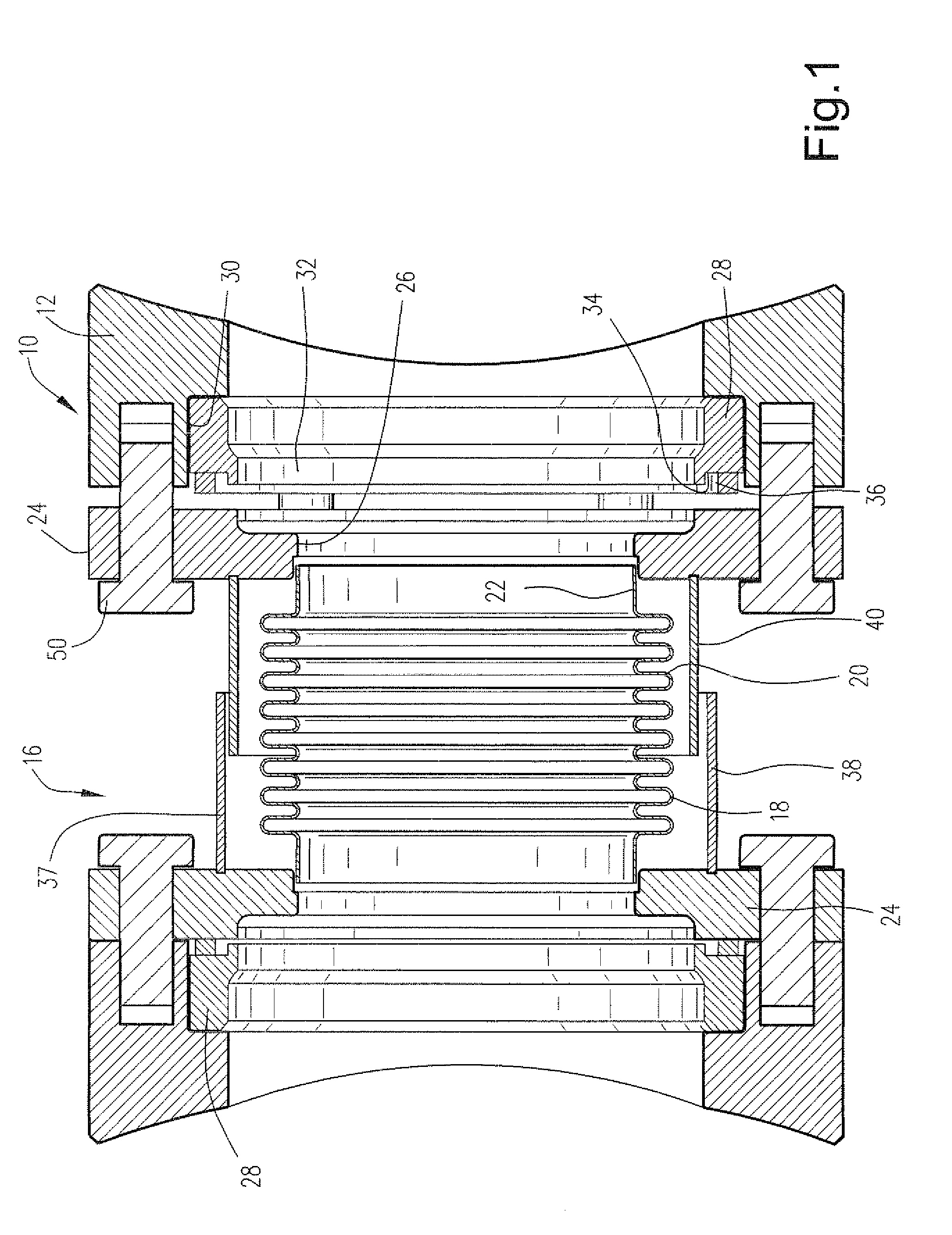
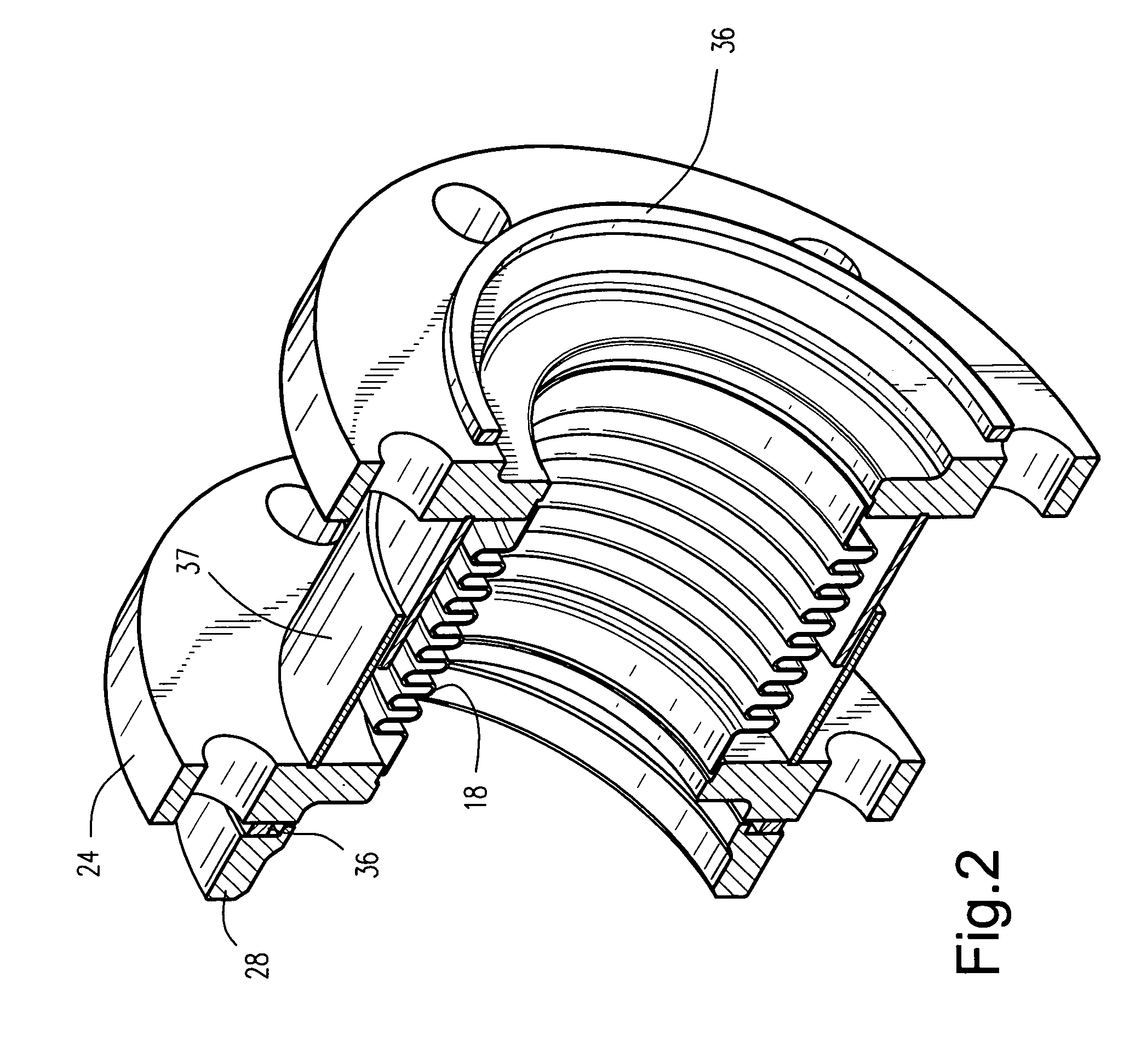
[0007]Referring to the drawings particularly to FIG. 1, there is illustrated an outer crossfire tube assembly generally designated 10 arranged between a pair of casing bosses 12 of adjacent combustors in a gas turbine. The bosses 12 are annular in nature and have facing bolt circle holes for securement of the crossfire tube assembly between the casing bosses. Arranged between the casing bosses 12 is an outer crossfire bellows assembly generally designated 16. Bellows assembly 16 includes a bellows 18 having inner and outer diameters defined by axially spaced convolutions 20. The bellows assembly 18 lies generally co-axial with and between the casing bosses 12 and terminates at opposite ends in cylindrical sections 22. A pair of annular flanges 24 are provided, each having an internal cylindrical opening 26 for receiving an end 22 of the bellows 18. The ends 22 of bellows 18 are sealed to the flanges 24, for example, by fillet type welds between the bellow's ends and the flanges form...


PUM


Abstract

A crossfire tube for attachment between casing bosses of combustors includes a bellows assembly having a bellows with opposite cylindrical ends welded to annular flanges. The annular flanges include a bolt circle for securing the flanges to the combustor bosses. The flanges bear against a gasket for sealing against inserts welded to the casing bosses for retrofit in the sealing assembly to combustors or to seats where the inserts and bosses are formed integrally during original equipment manufacture. A telescoping cylindrical sleeve surrounds the bellows to protect from falling foreign object damage.

Description

BACKGROUND OF THE INVENTION[0001]The present invention relates to a crossfire tube assembly for gas turbines and particularly relates to a crossfire tube assembly having a gasket / bellows combination for air tight sealing of the crossfire tube assembly.[0002]As well known, combustors in stationary land based gas turbines are interconnected by crossfire tubes. These crossfire tubes enable initial ignition of a combustor adjacent to an ignited combustor thereby eliminating the need for separate ignition, and corresponding elements for enabling separate ignition, from each combustor. Crossfire tubes are well known in the gas turbine environment. See for example U.S. Pat. Nos. 4,249,372 and 6,606,865. In the system disclosed in the latter patent, a bellows with annular rings at opposite ends is arranged between combustor flanges. While those bellows assemblies have performed and have demonstrated significant improvement over prior crossfire tube assemblies, the sealing capability of prio...

Claims


Application Information

Patent Timeline
Patent Type & Authority Patents(United States)
IPC IPC(8): F02C7/264F02C7/20
CPCF23R3/48
Inventor NICHOLS, RICHARD LEEHUTCHERSON, SARAH JANEBELSOM, KEITH CLETUSALMOND, III, THOMAS CHARLESCHANDRASHEKAR, NATESHNEGRONI, ALBERTO
Owner GE INFRASTRUCTURE TECH INT LLC
Why Eureka
Try Eureka