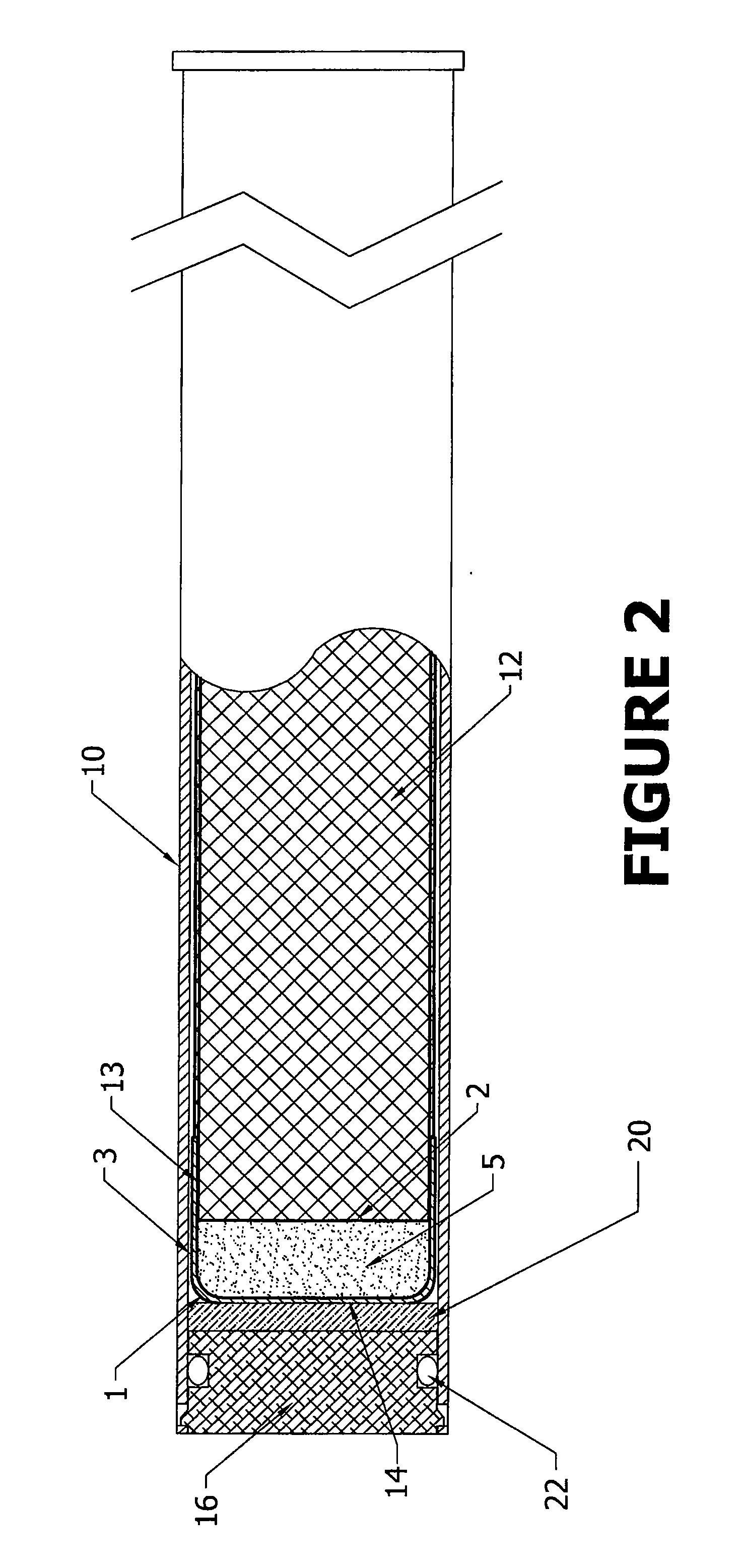
[0014]In one embodiment, an end cap is removably affixed to the open end of the
cartridge case. The end cap protects the standard low FOD weighted nose decoy flare from environmental conditions and handling issues which might damage the flare. The end cap is expelled as the flare is deployed from the aircraft.
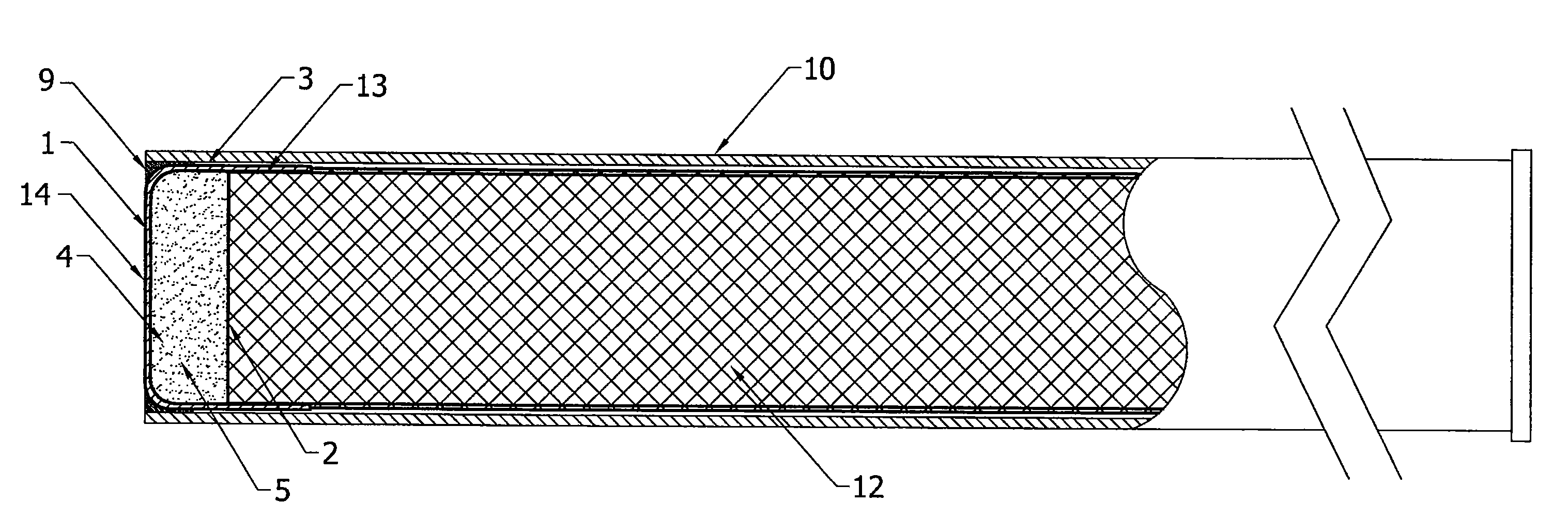
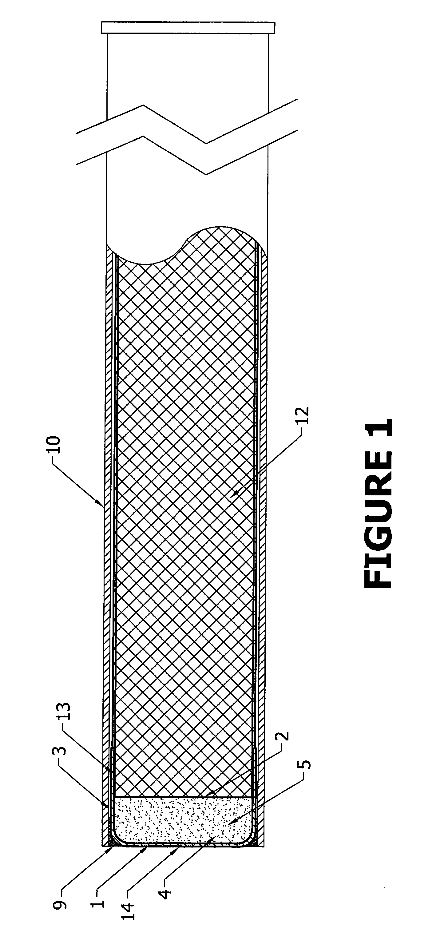
[0017]A nose cup, having a closed end, an open end, an internal cavity and at least one side wall surrounding the internal cavity, is adjacent to the forward end of the flare housing. The nose cup is made of a thin, light weight
metal, for example aluminum or plastic. A bulkhead is affixed to the forward end of the flare housing. The bulkhead seals off the forward end of the flare housing allowing the pressurization of the case thus facilitating propulsion. The internal cavity is intermediate to the closed end of the nose cup and the bulkhead. A
high density metal powder is disposed within the internal cavity. The
powder is capable of being jettisoned from the nose cup when the flare pellet subassembly is spent. Those of skill in the art will recognize that many
high density metal powders are suitable for this application such as
tungsten, iron, lead,
tungsten carbide, and Kinertium (
tungsten alloy).
[0019]It is beneficial in both the standard and kinematic low FOD weighted nose decoy flare
assembly to maximize the powder jettisoned once the flare pellet subassembly is spent. One means of maximizing the powder jettison is to alter the nose cup after the flare pellet subassembly is spent so that it becomes aerodynamically unstable and tumbles through the air thereby spilling the
metal powder. In one embodiment for use with a standard flare, the interface between the forward end of the flare pellet subassembly and the side wall of the nose cup is important. The heat from the burning of the flare also destroys a portion of the side wall of the nose cup. With the disintegration of its container, the powder is spilled from the nose cup. Additionally, the dimension change in the nose cup makes it aerodynamically unstable causing it to tumble through the air and spill its contents. In another embodiment for use with a kinematic flare, a mechanism is employed to separate the nose cup from the flare housing, for example by rupturing the nose cup. The force of the rupturing mechanism causes the nose cup to swing away from the bulkhead thereby jettisoning the powder from the nose cup.
[0021]In another embodiment for use with either a kinematic or standard flare, rapid
deflagration cord (RDC) is embedded in the
metal powder and in contact with the flare pellet subassembly. The RDC is ignited from the flare upon
burn out of the flare. Upon ignition, the RDC rapidly generates pressure in the nose cup which will jettison the metal powder from the nose cup. The RDC may be in any shape that promotes the ignition of the RDC and jettison of the metal powder, for example a coil shape may be used. In an embodiment where the flare is a kinematic flare, it is necessary to separate the nose cup and the flare housing. The ignition end of the RDC intersects the bulkhead and enters the flare housing so that it may contact the forward end of the flare pellet subassembly. The ignition end is positioned so that its ignition occurs upon the
burn out of the flare pellet subassembly. Upon ignition, the nose cup ruptures due to the pressure created by the burning RDC, causing the nose cup to separate from the bulkhead. Alternatively, a blend of metal powder and an energetic binder (for example GAP) may be added to the nose cup for use with either a standard or kinematic flare to increase the burning /
explosive force.
[0022]In yet another embodiment for use with a kinematic flare, a through-bulkhead initiator is employed as a means to separate the nose cup from the flare housing. A hole traverses the bulkhead from the flare housing to the nose cup. A
heat transfer conduit is disposed inside said hole. Said
heat transfer conduit has a
flange at one end internal to said flare housing which seals the flare housing. An internal cavity is disposed within said
heat transfer conduit and is axially aligned with said hole in said bulkhead. A first end of said cavity is adjacent to said
flange, a second end of said cavity is adjacent to said nose cup and has an opening adjacent to said nose cup. An
explosive material is disposed inside said internal cavity of said heat transfer conduit. The
flange is adjacent to the forward end of the flare pellet subassembly and heats up upon burn out of the flare pellet subassembly. Upon heating of the flange, the heat is transferred to through the heat transfer conduit to the
explosive material which ignites, rupturing the nose cup and expelling the powder from the nose cup thereby reducing the weight of the nose cup. In some embodiments, the flange of the heat transfer conduit has a
thin section aligned with the first end of said cavity thereby facilitating the heating of the
explosive material.
[0023]Accordingly, it is an object of the present invention to provide an improved aerodynamic
countermeasure flare wherein the nose weight is comprised of a
high density metallic powder contained in a cup-like container in the nose of the flare, where the powder is unconstrained and may flow out of the cup at the completion of the flare burn such that the remaining casing is a light-weight shell of much reduced danger as
foreign object damage. It is another object of the present invention to identify a metal powder dense enough to serve as an effective nose weight which changes the trajectory of the flare, but which is sufficiently dense as to not displace a significant amount of volume used by the flare pellet subassembly. Another object of the present invention is to design a light weight container to hold the metal powder. Yet another object of the present invention is to devise a means to maximize the powder jettison from the nose cup upon burn out of the flare.


