Cmc blade with pressurized internal cavity for erosion control

Active Publication Date: 2013-12-12
GENERAL ELECTRIC CO
View PDF5 Cites 8 Cited by
  • Summary
  • Abstract
  • Description
  • Claims
  • Application Information

AI Technical Summary

Benefits of technology

[0009]The present invention includes a new type of airfoil and CMC blade for use in a gas turbine engine having a design that ensures greater longevity, particularly in the event of damage to an airfoil caused by a foreign object impacting the blade. The invention provides a unique method of secondary blade protection by using dry, cool air to protect the structural integrity of the blade even after an in

Problems solved by technology

However, gas turbine engine temperatures often reach or exceed the limits of the materials of construction, thereby comprising the structural integrity of components in the hot sections of the engine, particularly the gas turbine engine blades.
One problem that has discouraged the introduction of new light weight composite gas turbine engine blades is their relative vulnerability to foreign object damage.
Smaller objects can erode the CMC blade material and eventually reduce the efficiency and degrade the performance of the engine.
Any impact by larger objects can rupture or pierce the blades, and portions of an impacted blade can even be torn loose and cause extensive secondary damage to adjacent and downstream blades or other vital engine components.
However, even the dissipation of the impact energy can cause the blade to locally oscillate and/or be displaced to a different amplitude, and ultimately fail.
Any oscillations or large rapid displacements of the trailing edge also induce strains to the blade matrix which c

Method used


Image

  • Cmc blade with pressurized internal cavity for erosion control
  • Cmc blade with pressurized internal cavity for erosion control
  • Cmc blade with pressurized internal cavity for erosion control

Examples


first embodiment

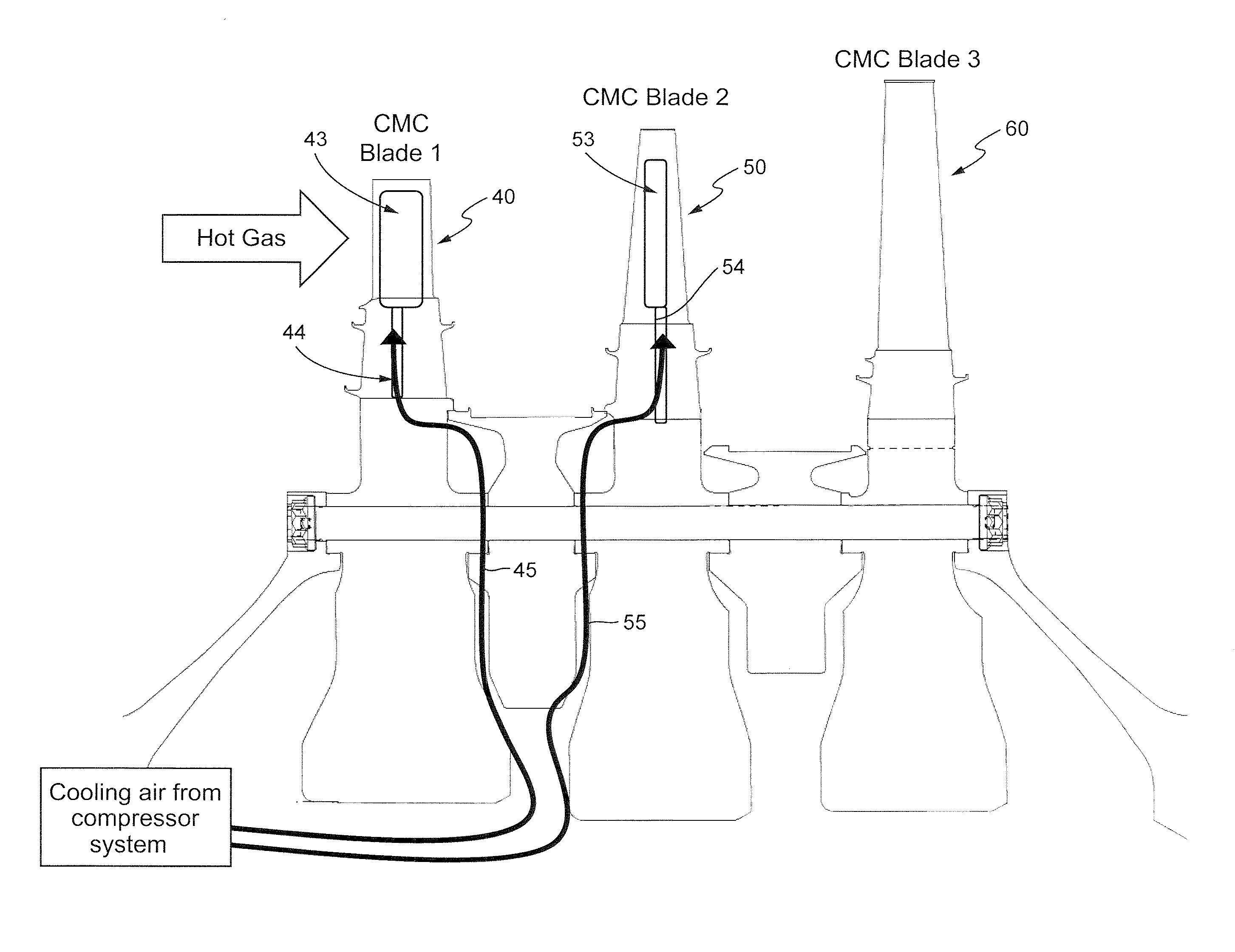
[0027]FIG. 1 also illustrates exemplary means for pressurizing the integral interior blade cavities in the invention via fluid openings 17 and 18. This type of bottom feed pressurization can be achieved by introducing a continuous air stream (ultimately creating a steady state internal pressure condition) into each blade cavity through blade openings 17 and 18 (see also FIGS. 3 and 4). The two air feeds extend from the bottom edge of the blade dovetail up through blade shank 15 into the CMC cavities. As noted above, pressurized air nominally is provided by an external pressure system (see FIG. 8).

second embodiment

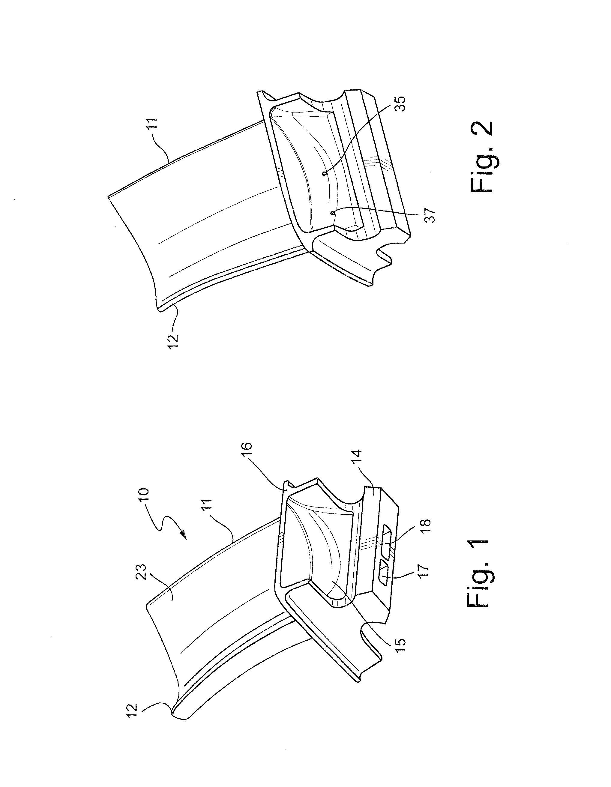
[0028]FIG. 2 is a perspective view of a CMC composite turbine blade having an alternative integral interior blade cavity pressurization system in a second embodiment as compared to FIG. 1. This shank-fed blade pressurization system provides a continuous air stream using separate internal feed passageways beginning in the blade shank and proceeding into the separate blade cavities as shown. Again, the air feed ultimately forms a steady state internal pressure condition in each blade cavity. However, in this embodiment the flow occurs via smaller blade air passageways 35 and 37. As in FIG. 1, the separate air feed lines extend from the bottom edge of the blade dovetail up through the blade shank into the separate CMC cavities. The pressurized air is again provided by an external air pressure system. The embodiment of FIG. 2 utilizes the same basic curved blade design with generally congruent interior cavities as in FIG. 1, with leading edge 11 and trailing edge 12.

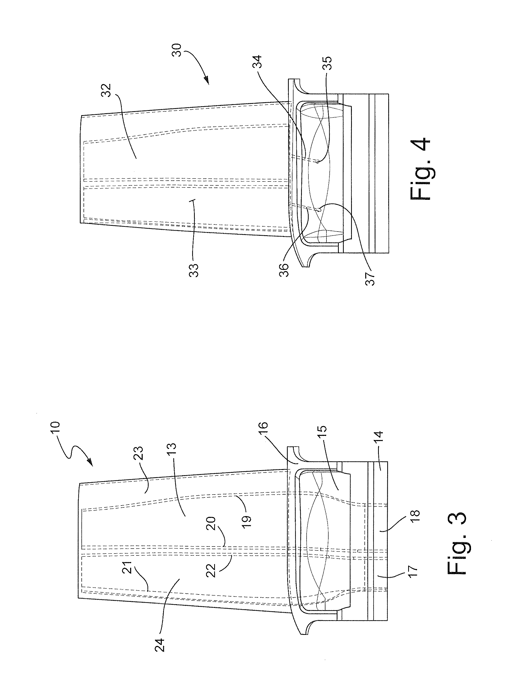
[0029]FIG. 3 is a fr...


PUM

PropertyMeasurementUnit
Temperatureaaaaaaaaaa
Lengthaaaaaaaaaa
Pressureaaaaaaaaaa

Abstract

A ceramic matrix composite blade for use in a gas turbine engine having an airfoil with leading and trailing edges and pressure and suction side surfaces, a blade shank secured to the lower end of each airfoil, one or more interior fluid cavities within the airfoil having inlet flow passages at the lower end which are in fluid communication with the blade shank, one or more passageways in the blade shank corresponding to each one of the interior fluid cavities and a fluid pump (or compressor) that provides pressurized fluid (nominally cool, dry air) to each one of the interior fluid cavities in each airfoil. The fluid (e.g., air) is sufficient in pressure and volume to maintain a minimum fluid flow to each of the interior fluid cavities in the event of a breach due to foreign object damage.

Description

[0001]This invention was made with Government support under Contract No. DE-FC26-05NT42643 awarded by the Department of Energy. The Government has certain rights in the invention.[0002]The present invention relates to ceramic matrix composite (“CMC”) blades for gas turbine engines used in the power generation and aircraft industries and, in particular, to a new form of CMC blade maintained under a fixed pressure to prevent the blade cavities from being compromised (which otherwise could lead to a catastrophic failure of the engine) due to foreign object damage occurring to the blades during extended periods of use.BACKGROUND OF THE INVENTION[0003]Over the years, the performance criteria of gas turbine engines has steadily increased with corresponding improvements in engine efficiency, better thrust-to-weight ratios, lower emissions and improved fuel consumption. However, gas turbine engine temperatures often reach or exceed the limits of the materials of construction, thereby compri...

Claims


Application Information

Patent Timeline
IPC IPC(8): F01D5/18
CPCF01D5/181F01D5/147F01D5/18F01D5/187F01D21/003F05D2300/6033Y10T29/49337Y02T50/60
Inventor GARCIA-CRESPO, ANDRES JOSEGOIKE, JEROME WALTER
Owner GENERAL ELECTRIC CO
Why Eureka
Try Eureka