Fan blade with segmented fan blade cover

a fan blade and fan blade technology, applied in the field of fan blades, can solve the problems of engine shutdown, engine failure, engine shutdown or lock, and other downstream engine components that may also damage other downstream engine components, so as to minimize the risk of damage to downstream components such as compressors and turbines

Active Publication Date: 2017-01-26
RTX CORP
View PDF4 Cites 7 Cited by
  • Summary
  • Abstract
  • Description
  • Claims
  • Application Information

AI Technical Summary

Benefits of technology

[0022]The covers for the suction side of the fan blade have been described above as including one or more slits. The term “slit” is intended to describe a weakened portion of the cover that is essentially linear. The term slit is intended to encompass any weakened line or narrow region that can divide the cover into distinct segments on either side of the weakened line or narrow region. Other suitable terms or embodiments include perforation, score, groove, slot, notch, etc. Further, the slits described above are described as transverse slits. The term transverse is intended to mean across the cover or extending between the leading edge and the trailing edge of the fan blade. The disclosed slits extend approximately in the direction of the airflow across the cover. One or more slits may be included so that the covers are divided into two or more segments. By dividing the cover into two or more segments, if a portion of the cover becomes detached from the fan blade body, the cover may break along the slit thereby sending only a single segment downstream instead of the entire cover. As a result, the risk of damage to downstream components such as the compressors and turbines is minimized.

Problems solved by technology

Partial or complete separation of the cover from one or more fan blades can cause damage to a downstream component of the engine.
Further, partial or complete separation of a cover may displace the center of gravity (center of mass) of the entire fan assembly from its central axis.
However, if the bearings fail, rotation of the fan about the displaced center of gravity may result in forces that may also damage other downstream engine components.
If an FBO event severely damages the engine, the engine may cease normal operation, shut down or lock, and consequently produce no further power.
However, despite the engine shut down, it is undesirable to stop rotation of the fan.
If rotation of the fan stops, the engine becomes an extreme source of aerodynamic drag for the aircraft.
Such drag would be particularly significant in a twin-engine aircraft, with one engine mounted to each wing nacelle.
Thus, in a twin-engine aircraft, the combination of drag from the shut down engine and thrust from the remaining engine would produce an excessive yawing moment not easily overcome by the aircraft rudder.
If a part or debris enters the high-pressure turbine, for example, centrifugal forces may cause the parts or debris to puncture one or both of the nacelles, the fuselage or allow the engine to detach from the aircraft or damage the wing.

Method used


Image

  • Fan blade with segmented fan blade cover
  • Fan blade with segmented fan blade cover
  • Fan blade with segmented fan blade cover

Examples


Embodiment Construction

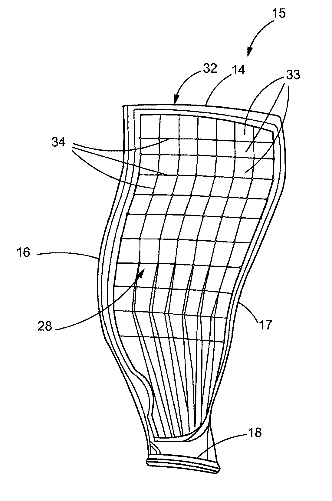
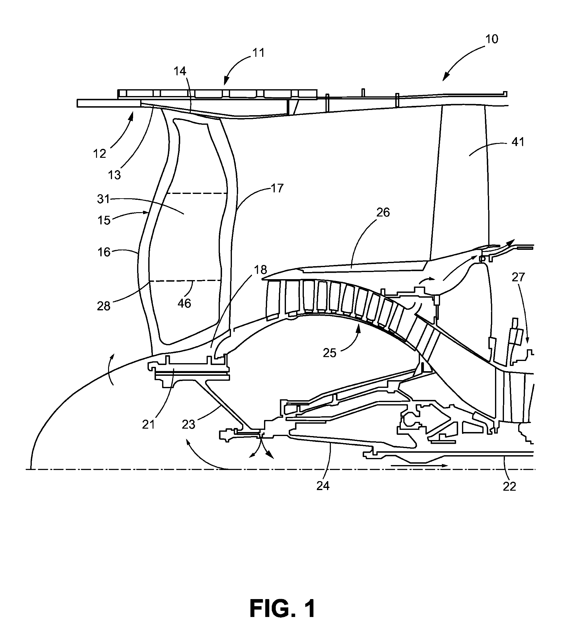
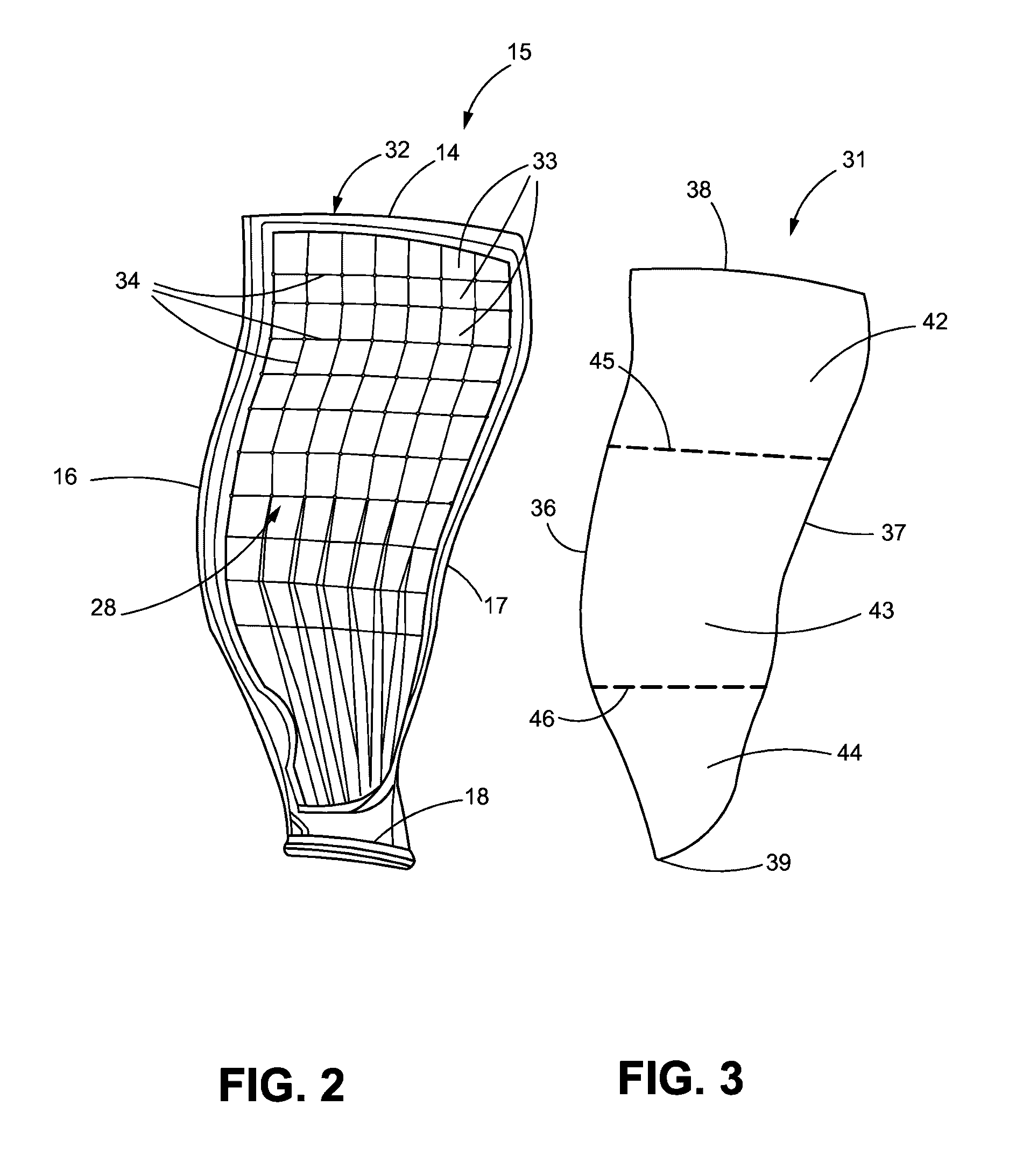
[0029]FIG. 1 illustrates part of a turbofan gas turbine engine 10. The engine 10 may include a nacelle 11, which may be lined with a fan case 12 that may include an abradable liner 13 for abuttingly engaging a tip 14 of a fan blade 15 as shown in FIG. 1. The fan blade 15 may include a leading edge 16, a trailing edge 17 and a base or root 18, which may be coupled to the hub 21. The hub 21 may be coupled to the low-pressure shaft 22 via the fan shaft 23 and fan shaft extension 24. Also shown in FIG. 1 is the low-pressure compressor 25, an annular bypass duct 26 and part of the high-pressure compressor 27. Downstream components such as a combustor and high and low-pressure turbines are not shown.

[0030]In addition to leading and trailing edges 16, 17 of the fan blade 15, FIG. 1 also shows the convex or suction side 28 of the fan blade 15, which is illustrated in greater detail in FIG. 2. FIG. 1 further illustrates a cover 31 that is disposed over the suction (or convex) side 28 of the ...


PUM


Abstract

A lightweight fan blade for use in turbofan gas turbine engines is disclosed. The fan blade includes a metallic body having a pressure side and a suction side. The suction side of the body includes one or more cavities. A cover is then attached to the suction side of the body to cover or enclose the one or more cavities. The cover includes one or more transverse weakened areas, such as a transverse slit so that the cover separates into one or more smaller segments in the event of a foreign object damage (FOD) or fan blade out (FBO) event occurs. The smaller segments of the cover are less likely to do damage to downstream components such as the low and high-pressure compressors. A single smaller segment of the cover may allow for continued operation of the engine because the imbalance created by the event may be tolerated by the engine.

Description

BACKGROUND[0001]Technical Field[0002]Disclosed herein are fan blades for turbofan gas turbine engines. In one example, a disclosed fan blade may include a metallic body having one or more hollow cavities for weight reduction and a segmented cover disposed on a the suction side of the fan blade and that encloses the hollow cavities. The disclosed segmented cover reduces the risk of damage to downstream engine components in the event of damage to the fan blade that causes partial or complete dislodgement of the cover from the fan blade.[0003]Description of the Related Art[0004]A geared turbofan engine is a type of turbofan airplane engine, similar to a turbojet. A geared turbofan engines, also known as a type of a gas turbine engine, may include a geared, ducted fan and a smaller diameter gas turbine engine mounted behind the fan that powers the fan. Part of the airstream passes through a core of the engine, which includes low and high-pressure compressors, a combustion chamber and hi...

Claims


Application Information

Patent Timeline
Patent Type & Authority Applications(United States)
IPC IPC(8): F04D29/38F04D29/02F04D29/32
CPCF04D29/388F04D29/023F04D29/325F01D5/147F01D5/282F01D21/045F05D2220/36F05D2230/72F05D2230/80Y02T50/60
Inventor ROCHE, CHARLES H.
Owner RTX CORP
Why Eureka
Try Eureka