Electrical connector system with power and command connectors

a technology of electrical connectors and power and command connectors, which is applied in the direction of coupling device connection, coupling parts engagement/disengagement, electrical apparatus, etc., can solve the problems of connector system damage and failure of upstream or downstream apparatus, and achieve the effect of minimizing the risk of damag

Active Publication Date: 2012-08-14
APTIV TECH LTD
View PDF9 Cites 11 Cited by
  • Summary
  • Abstract
  • Description
  • Claims
  • Application Information

AI Technical Summary

Benefits of technology

[0009]An object of the invention is to provide a connector system

Problems solved by technology

Those circumstances in combination with electrical current may cause a temperature rise and t

Method used


Image

  • Electrical connector system with power and command connectors
  • Electrical connector system with power and command connectors
  • Electrical connector system with power and command connectors

Examples


Embodiment Construction

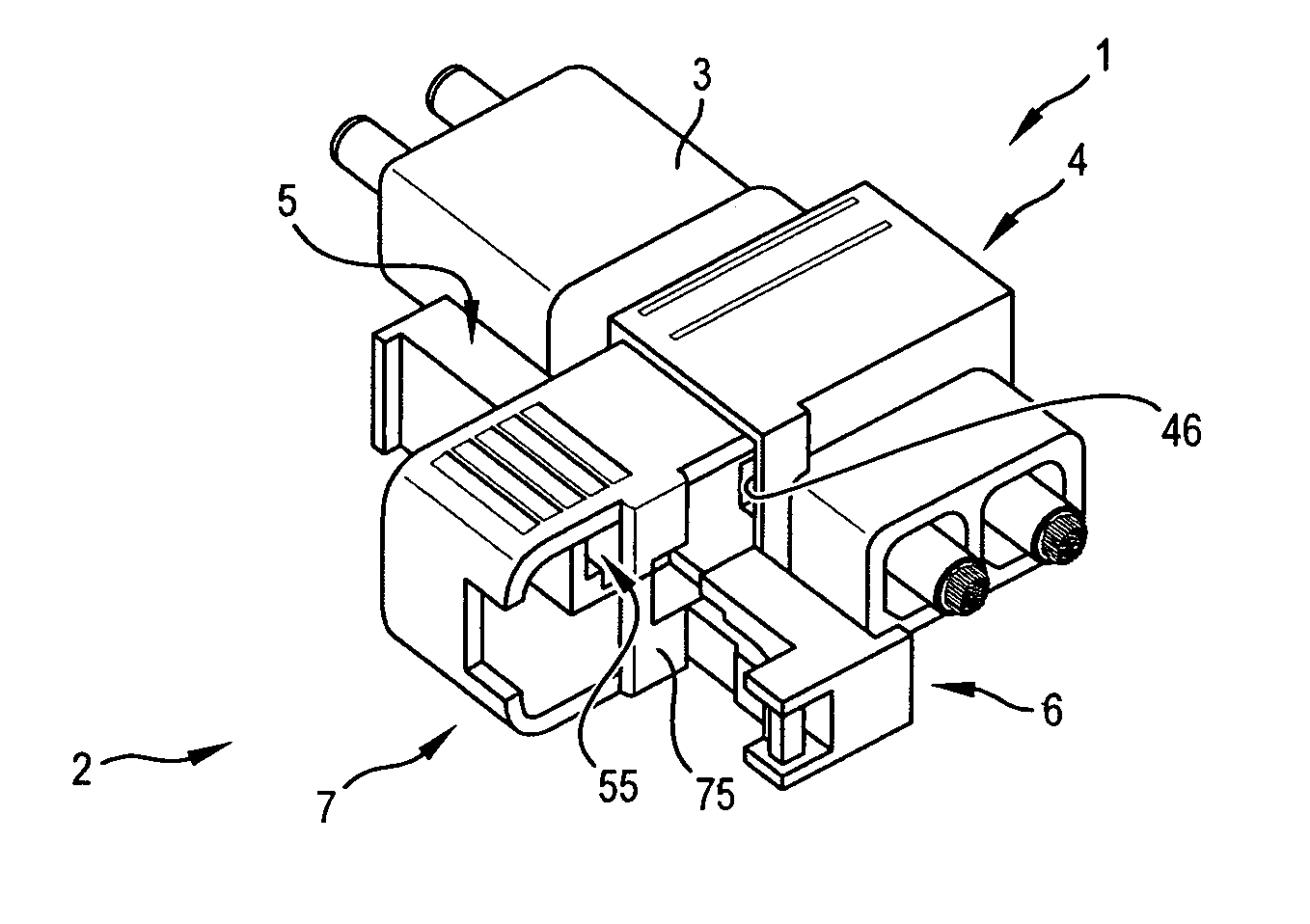
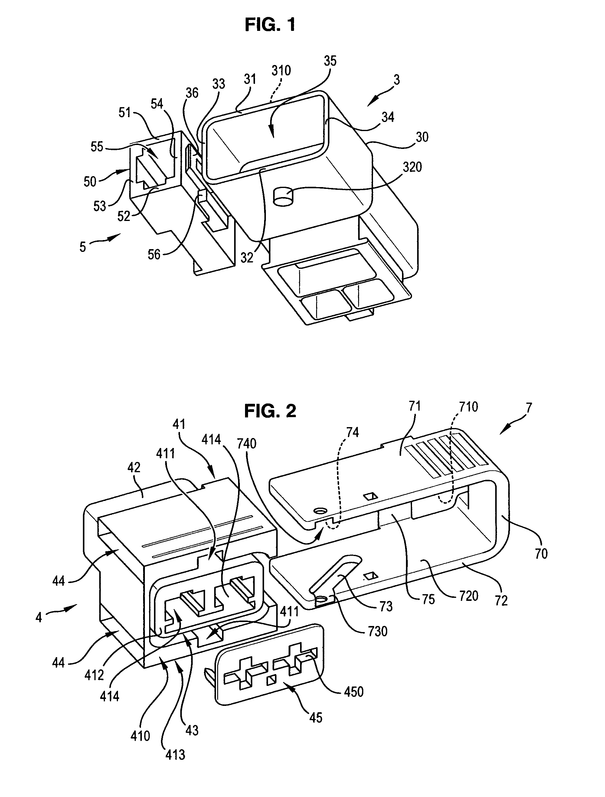
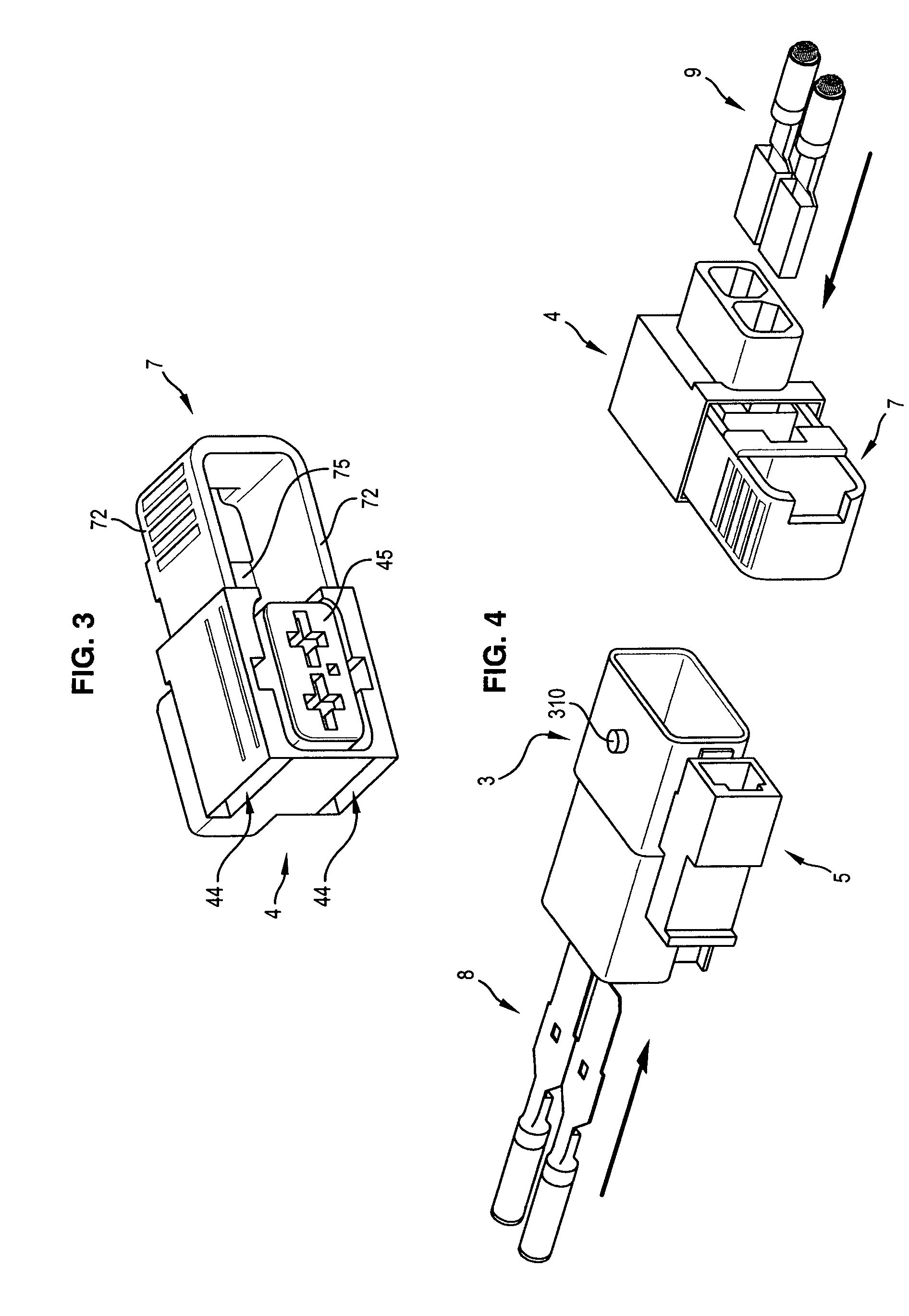
[0024]In a first embodiment shown on FIG. 5, the electrical connector system according to the present invention comprises:[0025]a first connector assembly 1, such as a power connector assembly, with a first connector 3 designed to be coupled with a corresponding second connector 4;[0026]a second connector assembly 2, such as a control connector assembly, with a third connector 6 designed to be coupled with a corresponding housing 5.

[0027]The material from which these connectors are made can vary. But they are preferably made of plastics or other like insulating material.

[0028]The three connectors 3, 4, 6 and the housing 5 are approximately of parallelepiped shape.

[0029]The first connector 3 is sized and shaped to receive the second connector 4 so as to perform a coupling according to a first plugging axis.

[0030]The housing 5 is sized and shaped to receive the third connector 6 so as to perform an electrical coupling according to a second plugging axis.

[0031]In this embodiment, the h...


PUM


Abstract

The present relates to an electrical connector system which includes a first connector assembly having a first connector and a second connector to be coupled one to the other; a second connector assembly having a third connector and a housing contiguous to the first connector, the housing having an open connecting face for receiving within a complementary part of the third connector so as to perform a coupling one to the other. This connector system may include a movable element which is movable between two positions, i.e.: a “first position” in which it masks at least partially the open connecting face, so that it makes impossible the coupling with the third connector; a “second position” in which it does not mask the front open connecting face, so that it makes possible the coupling with the third connector; the movable element being able to be moved into the “second position” only when said first and second connectors are fully coupled together.

Description

FIELD OF THE INVENTION[0001]The present invention relates to an electrical connector system.BACKGROUND OF THE INVENTION[0002]It is known electrical connector systems comprising:[0003]a first connector assembly having a first connector and a second connector to be coupled one to the other; and[0004]a second connector assembly having one connector (i.e. a third connector) or two connectors (i.e. a third connector and a fourth connector) to be coupled one to the other.[0005]Each connector comprises a housing with terminals adapted to make electrical contact with complementary terminals of the complementary connector to be coupled with.[0006]This type of electrical connector system may be used as a part of an overall electrical system for connecting an actuator to a power source and a control source. For example, the connector system may be used as a part of a power steering or an electrical brake of a motor vehicle, or a control system of an electrical traction motor of a hybrid vehicl...

Claims


Application Information

Patent Timeline
IPC IPC(8): H01R13/62
CPCH01R13/62905H01R13/639H01R13/62911
Inventor MULOT, GERARDCASSES, CLAUDE
Owner APTIV TECH LTD
Why Eureka
Try Eureka