Device and method for forming a stack of sheets on a delivery surface

a technology of a delivery surface and a stacking device, which is applied in the direction of pile receivers, thin material handling, article delivery, etc., to achieve the effect of preventing the wear of the contact surface between the guide elements and the structural elements and minimising the risk of damag

Active Publication Date: 2005-11-10
OCE TECH
View PDF20 Cites 4 Cited by
  • Summary
  • Abstract
  • Description
  • Claims
  • Application Information

AI Technical Summary

Benefits of technology

[0008] In another embodiment according to the present invention, the guide is controlled by the pusher element. As a result, the movement of the guide can be synchronised with the movement of the pusher element. In this way, on each pushing movement the relevant freedom of movement of the sheet edge is already sufficiently limited, so that the sheet cannot be deflected by the action of the pusher element but really is moved against the stop and damage to the surface of the sheet to be deposited on the stack due to the repeating movement of the pusher element is prevented.
[0009] In another embodiment according to the present invention, the guide is controlled by an electric drive. In this way it is possible to control the movement electronically and to act on any deviating situations during the receiving process.
[0010] In still another embodiment according to the present invention, the position of the guide path formed in the guide is adapted to the stack height. In this way, during the build-up of the stack it is always possible to ensure that any risk of damage is minimised.
[0011] In another embodiment, the two guide elements co-operate with one another by means of a spring force. As a result, the two parts can be closed in the position of rest and be opened if necessary, for example to receive a new sheet. In a further improvement, such opening is achieved by a structural element which is situated on the pusher element. In a further improvement this structural element is constructed as a leaf spring. In this way flexible opening of the guide elements can be achieved while wear of the contact surfaces between the guide elements and the structural element is prevented.

Problems solved by technology

As a result, any curl in the delivered sheets, in both the upward and downward direction, can be limited during at least part of the pushing movement, so that the sheet cannot be deflected as a result of the pusher element action but really is moved against the stop.

Method used


Image

  • Device and method for forming a stack of sheets on a delivery surface
  • Device and method for forming a stack of sheets on a delivery surface
  • Device and method for forming a stack of sheets on a delivery surface

Examples


Embodiment Construction

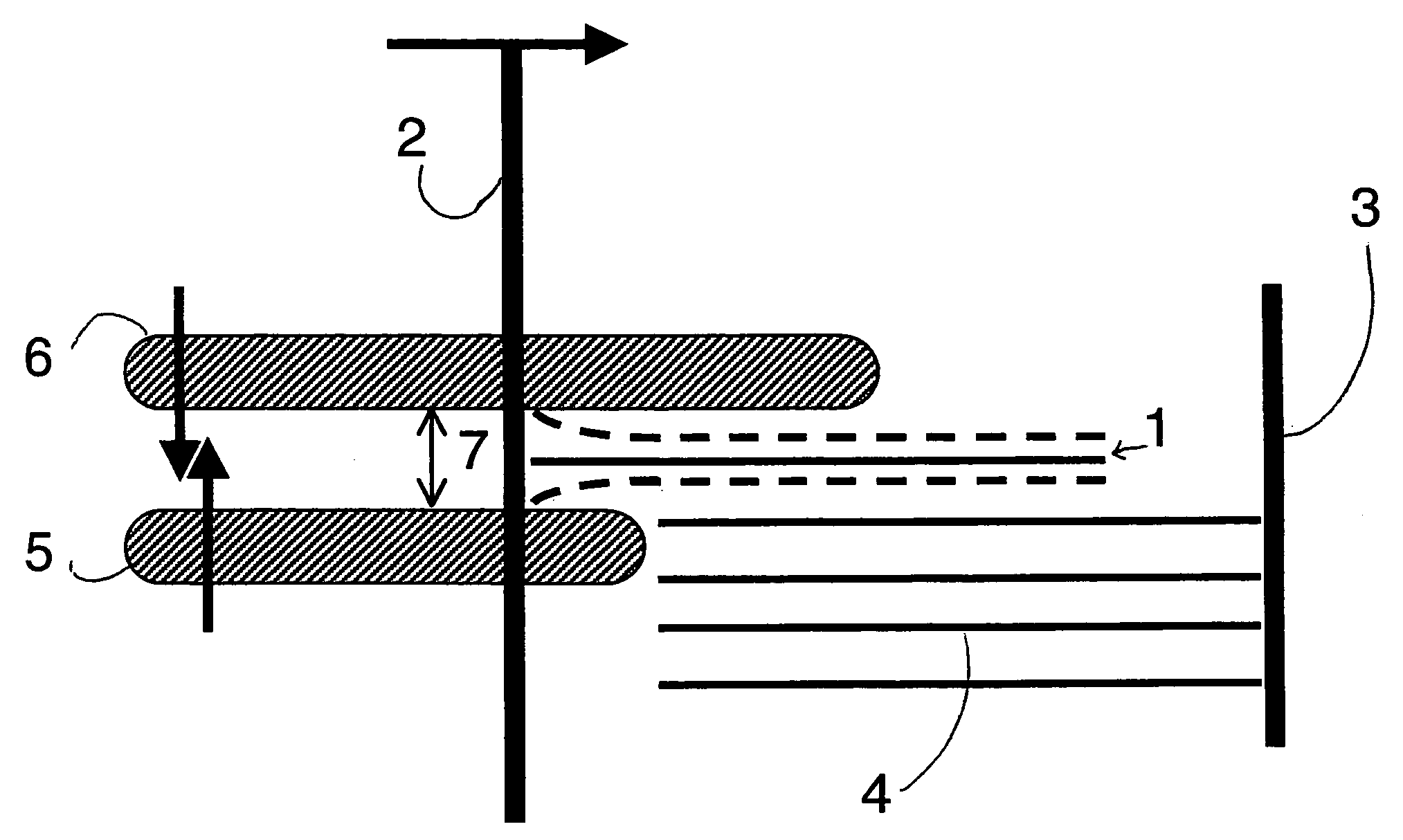
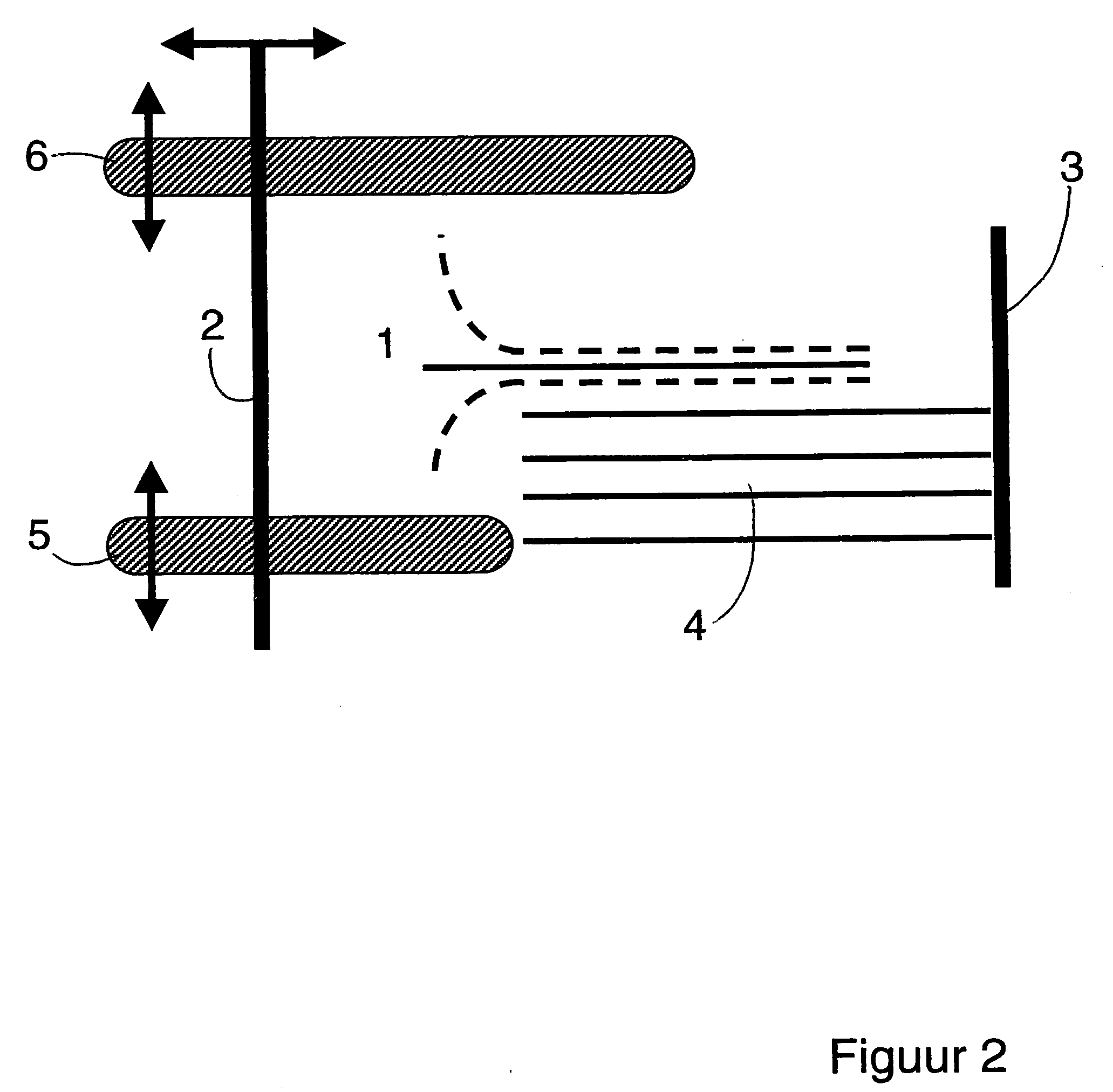
[0024]FIG. 1 illustrates the problem which may occur when sheets which are curled during collection are straightened for possible after-treatment or removal from the stack. As a result of the straightening or jogging of sheets which are placed on the top of a stack, thin sheets or sheets which are curled, for example due to the influence of bends in the machine paper path, or damp or temperature differences, may be incorrectly positioned against the stop and after numerous impacts may even be damaged to varying degrees and / or not be bound together with the other sheets in the stack. This effect is undesirable. This problem manifests itself particularly in systems having high capacity, high output speeds and a large variety of substrate materials. After-treatment stations must always be able to operate more rapidly and be able to handle an ever-increasing variety of materials and in practice it must be possible to change over from very thin and flimsy paper to thick and stiff paper. ...


PUM


Abstract

A method and device for forming a stack of sheets including a delivery surface, and also a stop and a pusher element movable in the direction of the stop, and also a guide which can occupy a first and a second position, in which the first position a sheet can be received in the guide, and in which the second position a guide path is formed, wherein the freedom of movement of the sheet edge is substantially limited in a direction substantially perpendicular to the pushing direction and substantially perpendicular to the delivery surface of the preceding sheet.

Description

[0001] This application claims the priority benefit of The Netherlands Patent Application No. 1026119 filed on May 5, 2004, which is hereby incorporated by reference. BACKGROUND OF THE INVENTION [0002] The present invention relates to a method of forming a stack of sheets on a delivery surface which includes the steps of depositing a sheet and, with the use of a pusher element, pushing against an edge of the sheet in order to apply the sheet against a stop. The present invention also relates to a device for forming a stack of sheets using the present method said device including a delivery surface and a stop and a pusher element movable in the direction of the stop. [0003] A method and device according to U.S. Pat. No. 5,054,766 is known wherein sheets are collected and arranged into a straight stack for after-treatment, for example, stapling, punching or stitching. A known application is the collection of printed sheets in a copying machine or printer. The collecting stations assoc...

Claims


Application Information

Patent Timeline
Patent Type & Authority Applications(United States)
IPC IPC(8): B65H29/46B65H29/52B65H31/36
CPCB65H2801/06B65H31/36
Inventor VAN OPSTAL, FRANCISCUS C.P.
Owner OCE TECH
Why Eureka
Try Eureka