Ultra-Miniature Electrochemical Cell And Fabrication Method

a technology of electrochemical cells and form factors, applied in the field of ultra-miniature electrochemical cells, can solve the problems of unsuitable methods, unfavorable application of extremely small cell electrode structures, and compound handling problems, so as to facilitate efficient repeatability and minimize the risk of electrode damage during handling

Inactive Publication Date: 2008-04-10
GENTCORP
View PDF4 Cites 9 Cited by
  • Summary
  • Abstract
  • Description
  • Claims
  • Application Information

AI Technical Summary

Benefits of technology

[0008]The foregoing problems are solved and an advance in the art is provided by an ultra-miniature electrochemical cell and related fabrication method. The cell includes a cell case having a first cell electrode attached to an inside wall thereof. An electrode-header assembly is also disposed in the cell case. The electrode-header assembly includes an electrode plug providing a second cell electrode, a header assembly attached to the cell case, and a current collector embedded in the electrode plug and extending through the header assembly. The cell further includes an electrolyte-carrying separator disposed in cell case between the first and second electrodes. Advantageously, ...

Problems solved by technology

This is a challenge when using high energy density cathode materials such as carbon monofluoride (CFx), manganese dioxide (MnO2) and silver vanadium oxide (SVO).
Whereas cylindrical cell electrodes made from such cathode materials are typically fabricated by extrusion, shearing and drying, these methods are unsuitable when the finished cathode diameter is less than a few millimeters because of the difficult...

Method used


Image

  • Ultra-Miniature Electrochemical Cell And Fabrication Method
  • Ultra-Miniature Electrochemical Cell And Fabrication Method
  • Ultra-Miniature Electrochemical Cell And Fabrication Method

Examples


Embodiment Construction

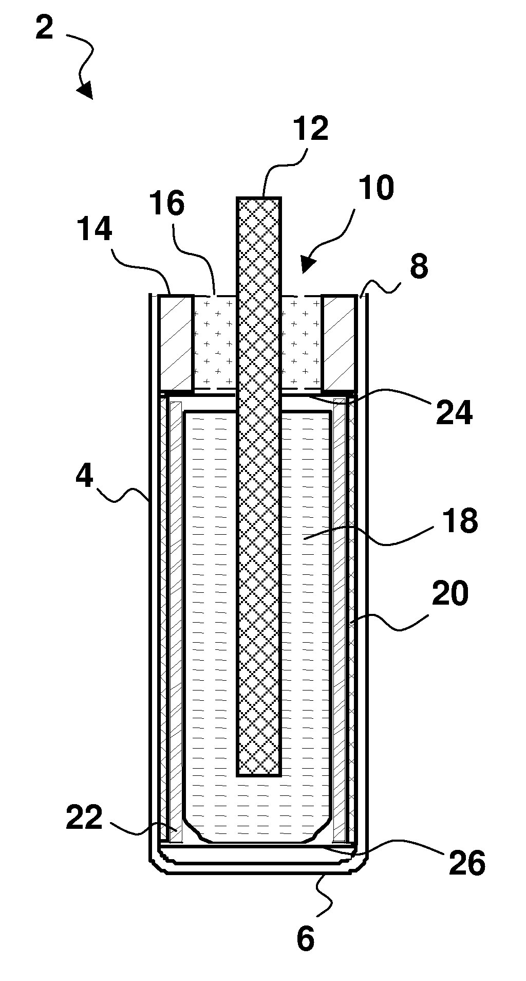
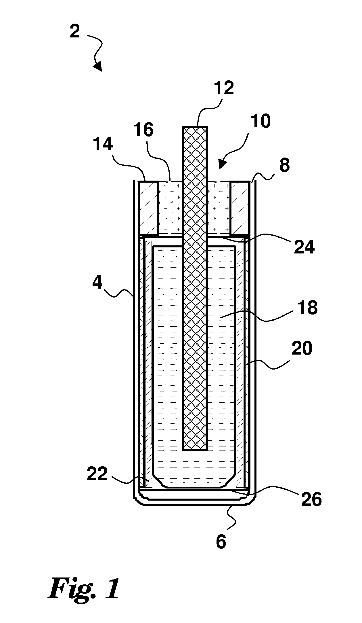
[0018]Turning now to the Drawings, wherein like reference numerals signify like elements in all of the several views, FIG. 1 illustrates an exemplary electrochemical cell 2 that may be constructed in accordance with the fabrication method disclosed herein. The cell 2 includes a case 4 whose configuration is that of a cylinder with one closed end 6 and one open end 8. The case 4 may be fabricated from titanium, stainless steel or any other suitable electrically conductive material. The open end 8 of the cell case 4 is sealed by a current collector header assembly 10 that comprises a current collector pin 12 sealed within an annular metal ring 14 by way of a glass seal 16. The annular ring 14 may be welded to the perimeter of the case open end 8 to provide a hermetic enclosure for the cell contents. The current collector pin 12 provides an electrical connection to a cathode structure 18 within the case 4. A cell anode 20 having a tubular shape is swaged against the inside wall of the ...


PUM

PropertyMeasurementUnit
Thicknessaaaaaaaaaa
Electrical conductoraaaaaaaaaa

Abstract

An ultra-miniature electrochemical cell and related fabrication method. The cell includes a cell case having a first cell electrode attached to an inside wall thereof. An electrode-header assembly is also disposed in the cell case. The electrode-header assembly includes an electrode plug providing a second cell electrode, a header assembly attached to the cell case, and a current collector embedded in the electrode plug and extending through the header assembly. The cell further includes an electrolyte-carrying separator disposed in cell case between the first and second electrodes. Advantageously, the second cell electrode may be fabricated using a punching process and joined to the current collector while constrained within tooling in order to minimize the risk of damage to the electrode during handling. This method facilitates the efficient, repeatable fabrication of small uniform electrodes and subsequent attachment of the electrodes to their associated current collectors. The method thus enables the production of electrodes having single millimeter thicknesses or less. Moreover, the method is compatible with many primary cell electrode materials, thereby allowing the production of primary power sources having a form factor and dimensions suitable for percutaneous injection.

Description

BACKGROUND OF THE INVENTION[0001]1. Field of the Invention[0002]The present invention relates to electrochemical cells and, more particularly, to cells with a very small form factor.[0003]2. Description of Prior Art[0004]Electrochemical cells of small size have been utilized for many applications. For example, miniature cells and batteries that utilize an alkali metal anode (such as lithium), a cathode, and a non-aqueous electrolyte have been widely used to power implantable medical devices, such as pacemakers. Such cells have been manufactured in a variety of shapes and sizes. In instances where the finished cell is to take the form of a cylinder, the electrode couple comprising anode, cathode and electrolyte materials may be fabricated as a thin, flat ribbon laminate that is rolled before insertion into the cell (jelly-roll). According to an alternative fabrication technique, cathode material may be formed into a hollow cylindrical bobbin that is inserted within a metal enclosure....

Claims


Application Information

Patent Timeline
IPC IPC(8): H01M2/14H01M6/00H01M50/147H01M50/593
CPCH01M2/0404H01M2/0426H01M2/065Y10T29/49108H01M4/5835H01M6/005H01M6/16H01M4/382H01M50/169H01M50/147H01M50/186H01M50/191H01M50/593
Inventor PYSZCZEK, MICHAELZAYATZ, ROBERT
Owner GENTCORP
Why Eureka
Try Eureka