Method for generating a circular periodic structure on a basic support material

a technology of a basic support material and a circular structure, which is applied in the direction of mechanical recording, photomechanical equipment, instruments, etc., can solve the problems of reducing the size of a magnetic bit cell, affecting the degree of minimization, and unable to achieve the increase of areal density, so as to achieve a higher throughput and minimize the risk of damaging the mask at high fluen

Active Publication Date: 2006-05-11
EULITHA
View PDF8 Cites 12 Cited by
  • Summary
  • Abstract
  • Description
  • Claims
  • Application Information

AI Technical Summary

Benefits of technology

[0019] In order to create diffracted beams, the transmission diffraction masks are either of absorption or of phase shifting type or a combination of the two types. Whereby it may be remarked that the throughput is higher using the phase shifting type since the diffraction efficiency and hence the use of the light from the light source is more efficient. Another advantage of using a phase mask is that the risk of damaging the mask at high fluences is minimized since no or little light is absorbed by the mask itself.

Problems solved by technology

Consequently, the increase of the areal density can only be achieved by a decrease of the size of a magnetic bit cell.
However, the level of minimization will touch physical limits due to the so-called super-paramagnetic limit which is touched when the size of grains become too small to retain its magnetization at room temperature for a sufficient period of time.
A major obstacle to the realization of a patterned magnetic storage media is the difficulty of a mass production of a suitable patterned substrate at an acceptable cost.
Electron beam lithography is capable of producing such patterns but the throughput is far from being acceptable.
However, up to now interference lithography has been shown to create only linear periodic structures such as arrays of lines or arrays of dots on square, rectangular or hexagonal grids.

Method used


Image

  • Method for generating a circular periodic structure on a basic support material
  • Method for generating a circular periodic structure on a basic support material
  • Method for generating a circular periodic structure on a basic support material

Examples


Embodiment Construction

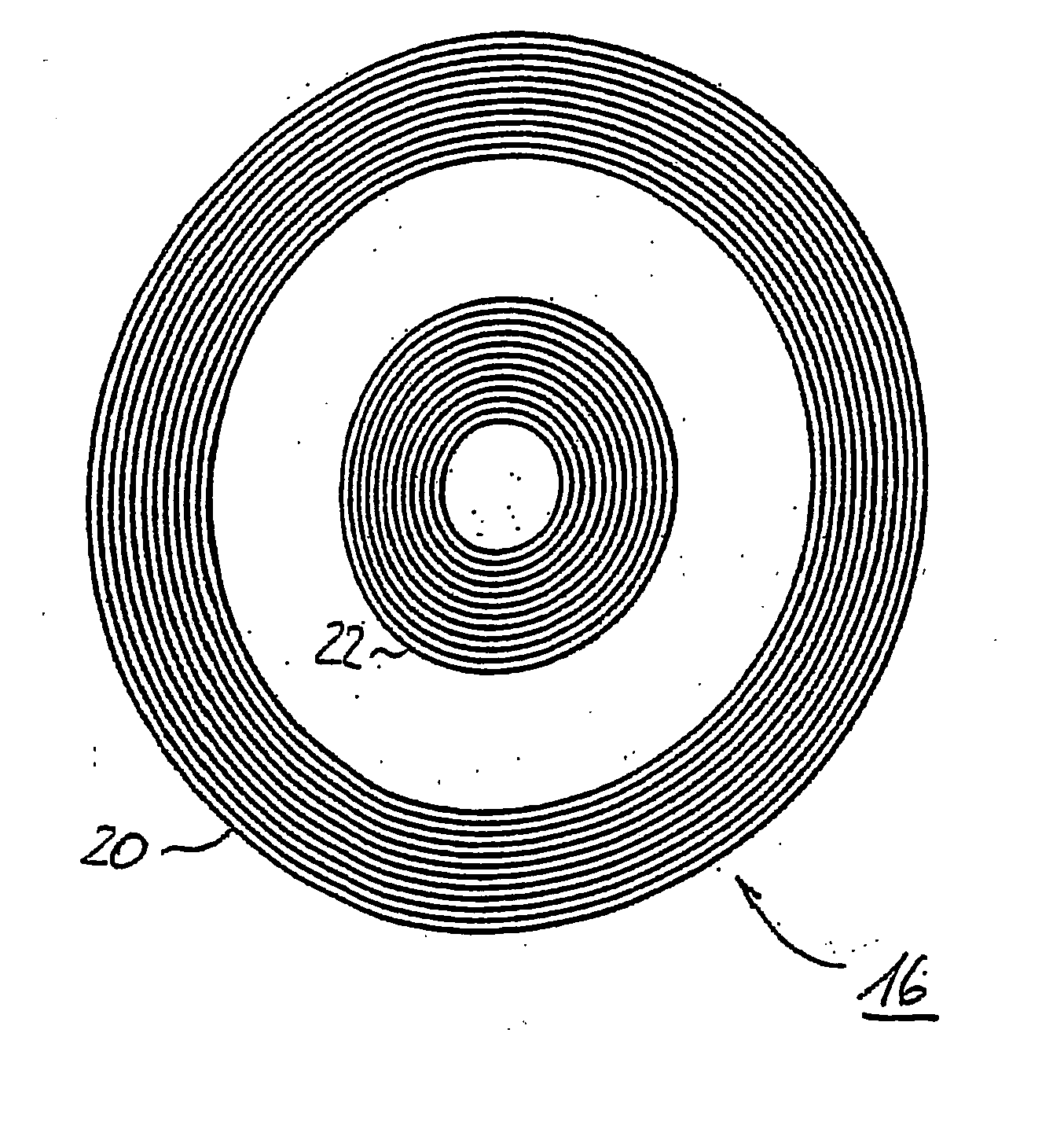
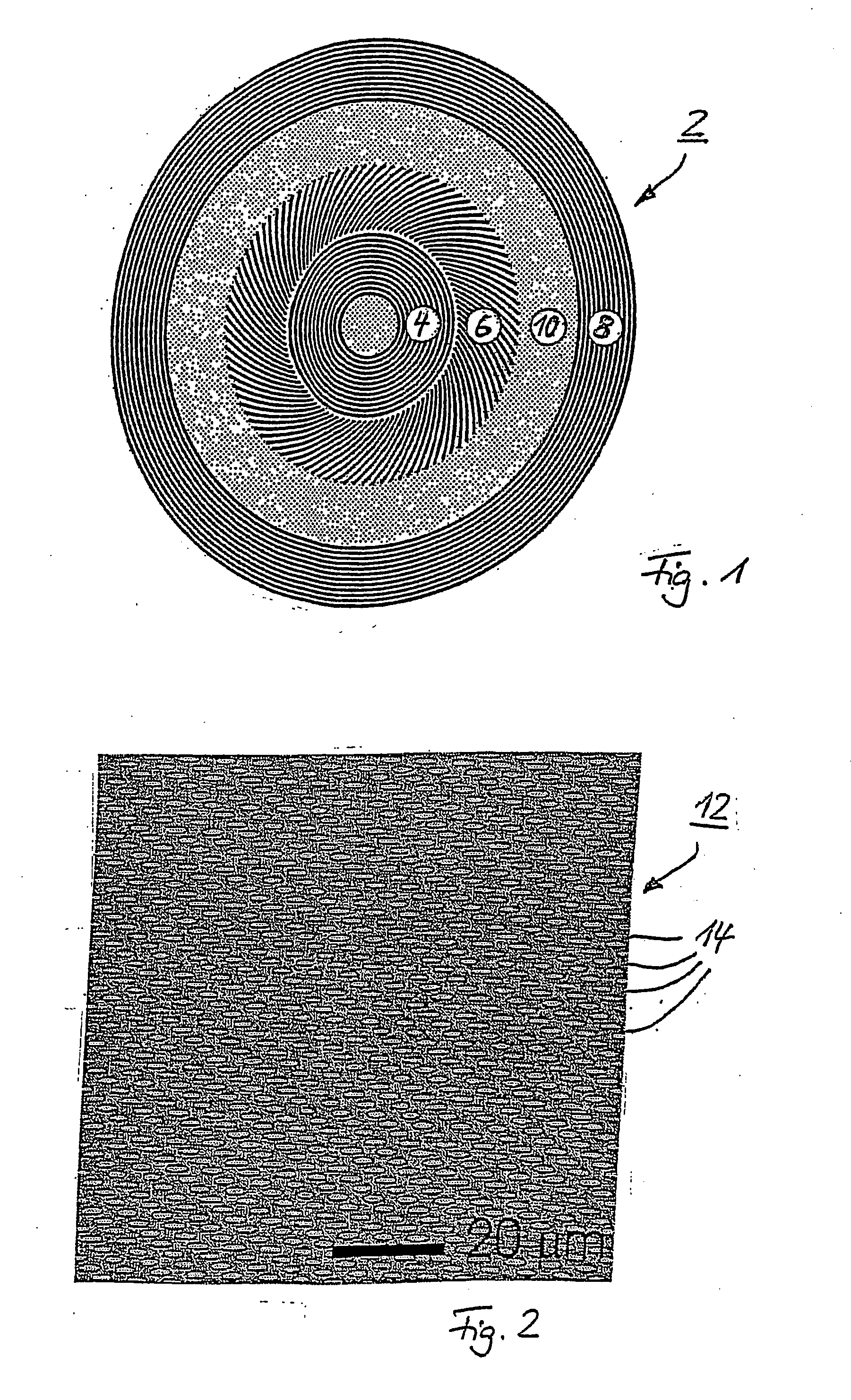
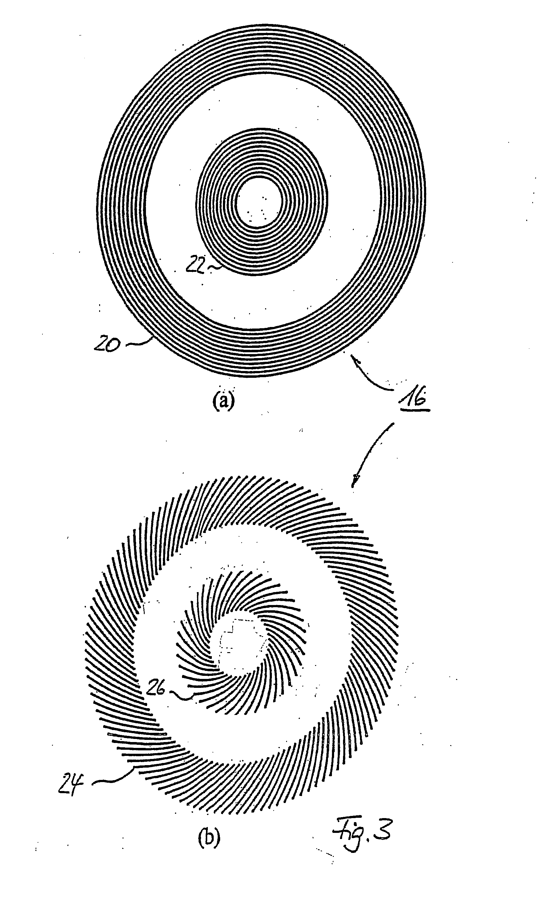
[0032] Generally, the method for generating a circular periodic structure for magnetic storage media starts with the design of a suitable number of transmission diffraction gratings. At least two of those gratings will create the desired interference pattern when illuminated by spatially coherent light. FIG. 1 therefore shows a schematic layout of a first transmission diffraction grating configuration 2 which comprises three different types of transmission diffraction gratings 4, 6 and 8. These gratings 4, 6 and 8 have the design to generate a pattern of periodic partitioned dots 14 on circular tracks. When illuminated with spatially coherent light this mask design yields an interference pattern with periodic intensity peaks along circular tracks as shown in FIG. 2 that depicts an optical micrograph of an array of holes (dots) 14 in a photoresist layer 12 obtained with the first transmission diffraction grating configuration 2. The holes / dots 14 are positioned along circular tracks ...


PUM

PropertyMeasurementUnit
wavelengthaaaaaaaaaa
refractive indexaaaaaaaaaa

Abstract

The present invention is directed to a method for the generation of periodic curved structures in a basic support material such as the basic layer for the magnetic bit cells of a magnetic storage device. The method includes the steps of generating a number of diffraction masks such that each mask comprises at least one transmission diffraction gratings having at least one of a different periodic concentric circular pattern, spiral-like periodic pattern and periodic radial spoke pattern; positioning at least one of the diffraction masks simultaneously or successively in a certain distance of the basic support material to be patterned, the distance being mask dependent; exposing the basic support material by directing light beams through each of the diffraction masks; and interfering the different light beams diffracted by the gratings on each mask in order to generate coincident light intensity patterns on the surface of the basic support material.

Description

CROSS REFERENCE TO RELATED APPLICATIONS [0001] The present application is a continuation of International Application PCT / EP2003 / 010233, filed Sep. 15, 2003 and further claims priority to European patent applications 03003392.2, 03007559.2 and 03011888.9, filed Feb. 14, 2003, Apr. 01, 2003 and May 27, 2003 respectively, all of the aforementioned incorporated herein by reference.BACKGROUND OF THE INVENTION [0002] The invention relates to a method for generating a periodic circular structure in a basic support material, such as for patterning a basic layer for the magnetic bits of a magnetic disk media. [0003] Magnetic recording devices in the form of circular discs coated uniformly with thin films of magnetic materials are used in many information systems. The data is recorded as magnetic bits in the thin film media. A magnetic bit means an area of the film that has been mainly magnetized in a direction by a writing head. The bits are read by a reading head which is sensitive to the ...

Claims


Application Information

Patent Timeline
Patent Type & Authority Applications(United States)
IPC IPC(8): G11B3/70G03F7/20
CPCG03F7/70283G03F7/70341G03F7/7035G03F7/70408G03F7/70466
Inventor DAVID, CHRISTIANSOLAK, HARUN
Owner EULITHA
Why Eureka
Try Eureka