Joint rod lock

a jointed bar and lock technology, applied in the direction of instruments, mechanical control devices, anti-theft devices, etc., can solve the problems of inability to realize the arrangement, the key must be taken along, and the risk of being lost, and achieve the effect of small construction size and simple operation

Active Publication Date: 2010-05-11
ABUS AUGUST BREMICKER SOEHNE AG
View PDF17 Cites 47 Cited by
  • Summary
  • Abstract
  • Description
  • Claims
  • Application Information

AI Technical Summary

Benefits of technology

[0006]It is the underlying object of the invention to provide a jointed bar lock having a combination locking mechanism which is simple to operate and whose lock body has a small construction size.

Problems solved by technology

It is, however, disadvantageous in this connection that a key necessarily has to be taken along which is furthermore at risk of being lost.
Such an arrangement can, however, not easily be realized with a jointed bar lock.

Method used


Image

  • Joint rod lock
  • Joint rod lock
  • Joint rod lock

Examples


Embodiment Construction

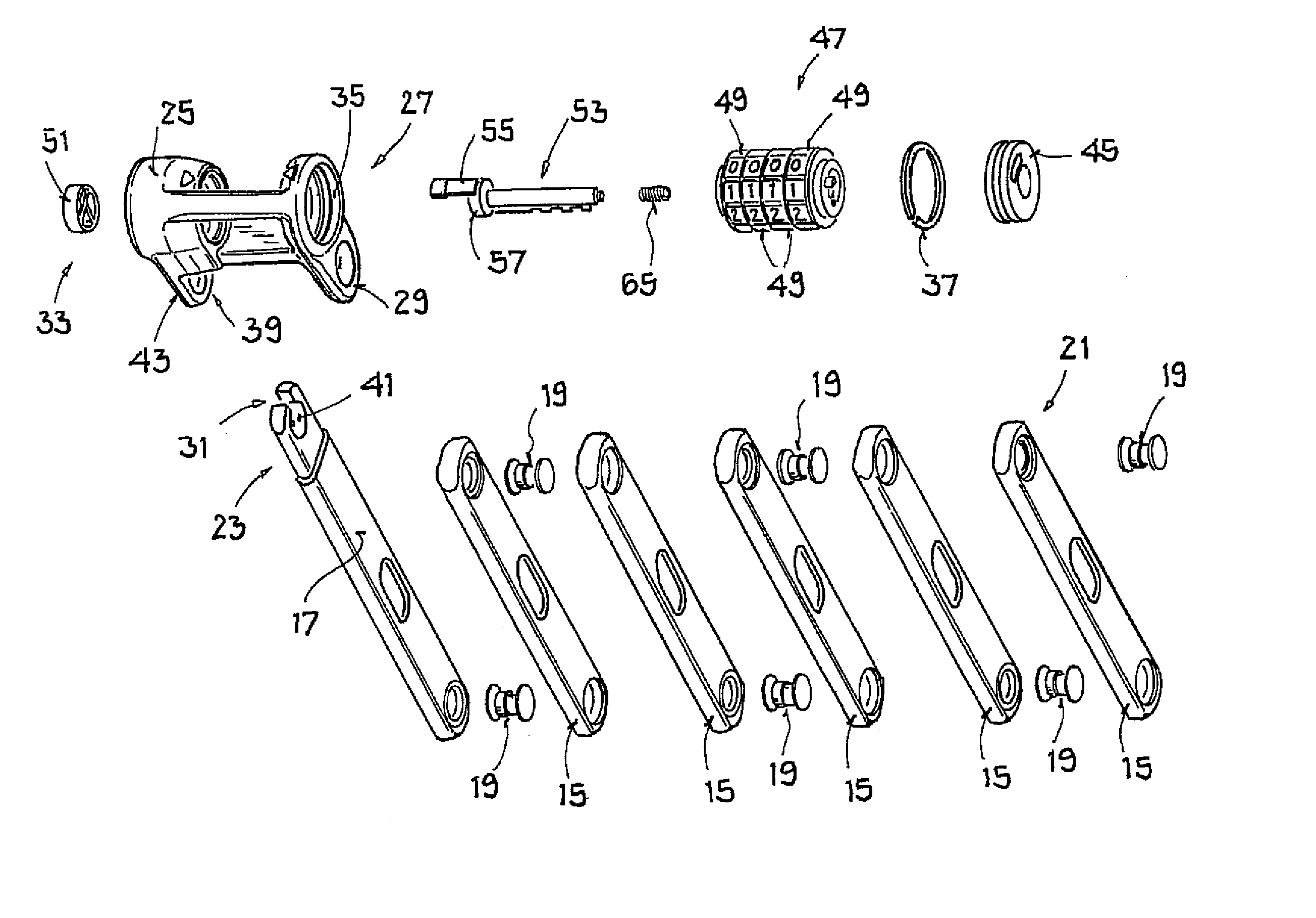
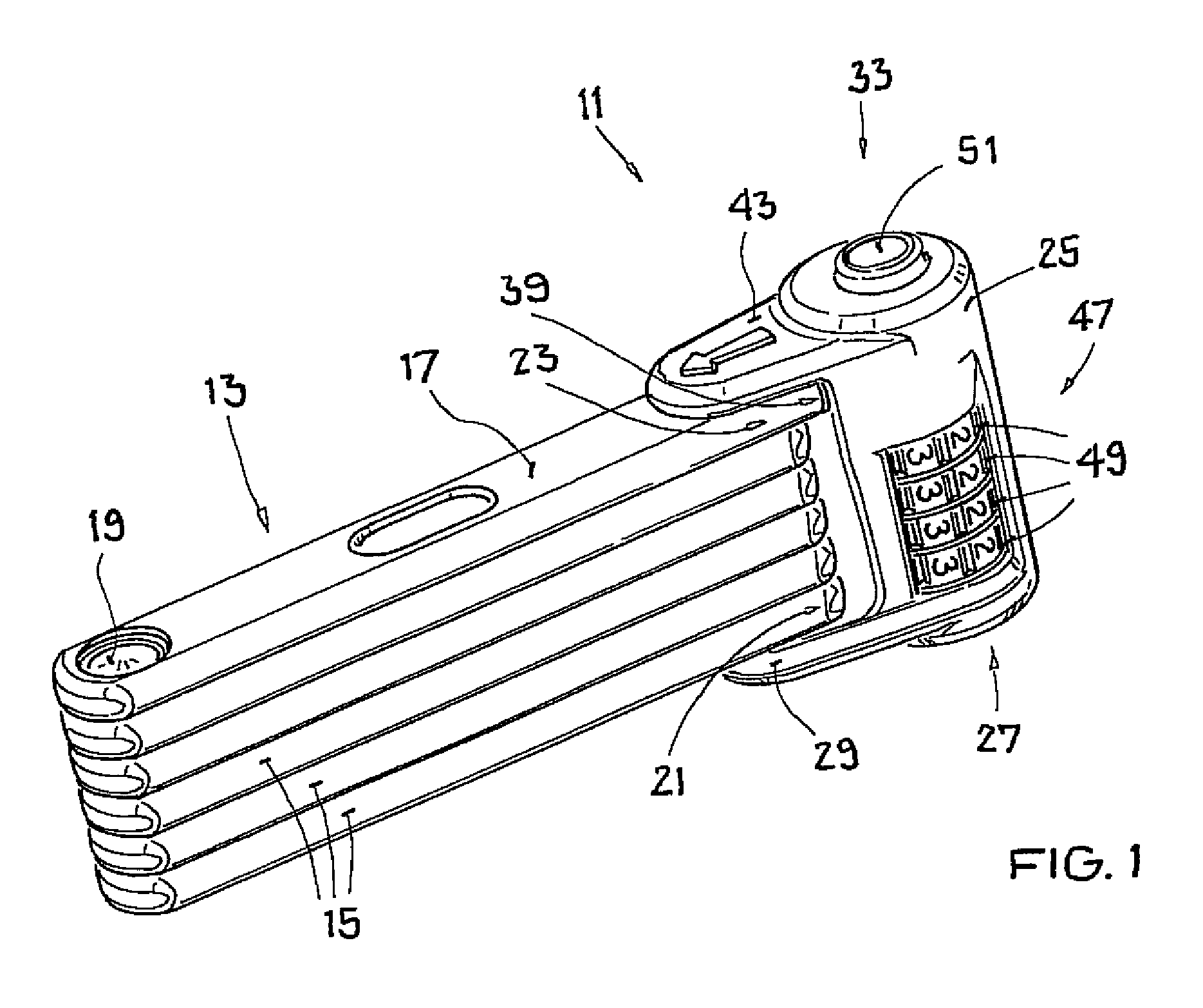
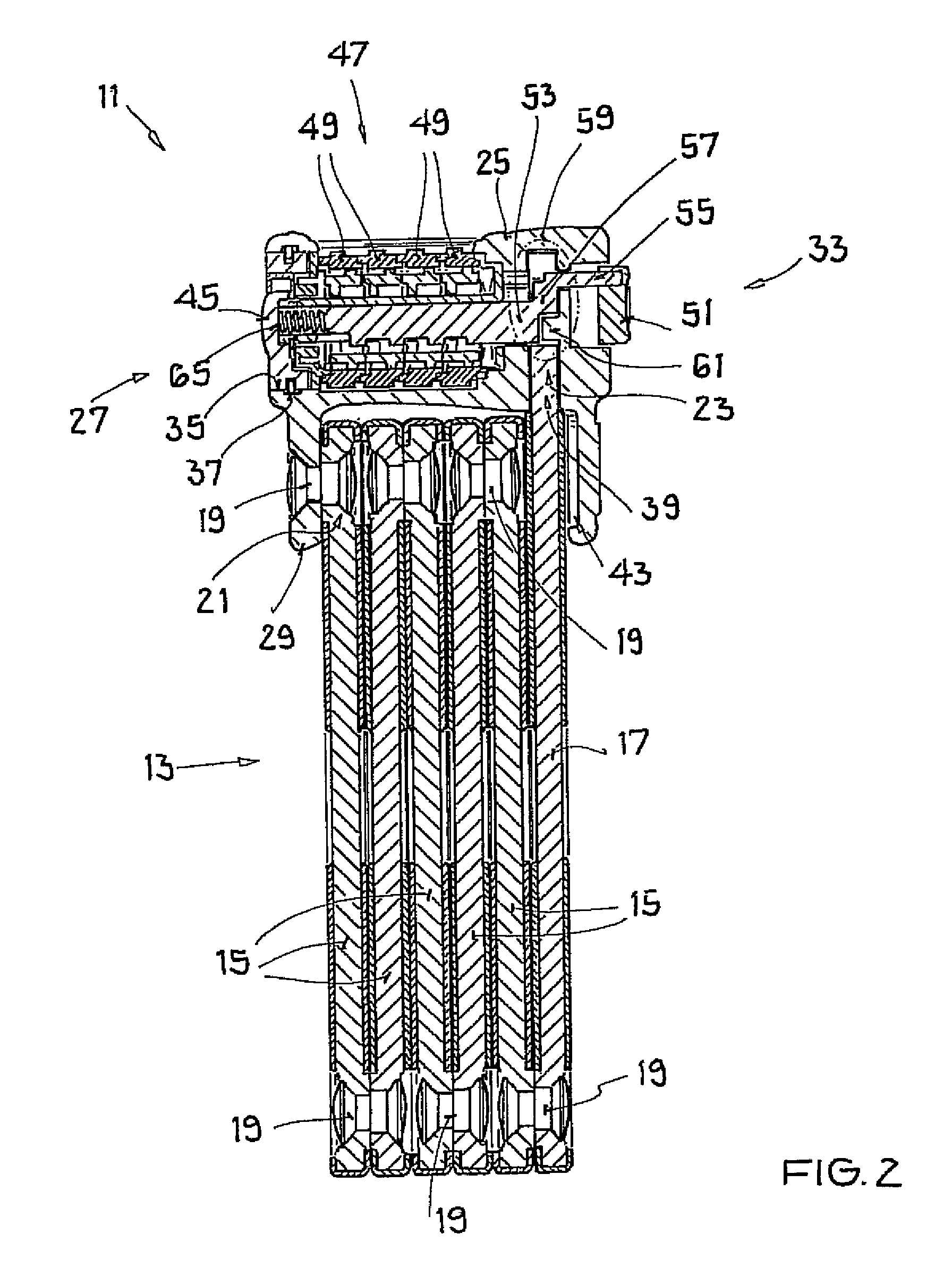
[0029]The jointed bar lock shown has a lock body 11 and a jointed bar hoop 13 fastened thereto. The jointed bar hoop 13 can, as is in particular shown in FIGS. 1 and 2, be folded together to form a compact unit and can also be latched to the lock body 11 in this state. The jointed bar hoop 13 can, however, also be folded apart (not shown) to form a loop in a manner known per se and hereby to lock a two-wheeler or to secure it to another object, for example a bicycle stand.

[0030]The jointed bar hoop 13 in detail has a plurality of jointed bars 15 of which one is formed as a locking bar 17. The jointed bars 15, 17 are each made flat and consist of hardened steel. The jointed bars 15, 17 are pivotally connected to one another in series by a respective rivet 19 such that the joint axes extend parallel to one another and the jointed bar hoop 13 can be folded together in the manner of a yardstick. In the folded together state of the jointed bar hoop 13, the longitudinal axes of the jointe...


PUM


Abstract

A jointed bar lock having a lock body and a jointed bar hoop which has a first end and a second end, said first end being permanently connected to the lock body and said second end being connectable to the lock body at a latching region of the lock body, with a bolt provided at the lock body selectively being movable into a latched position in which the bolt engages it the second end of the jointed bar hoop when it is connected to the lock body or is movable into a release position in which the second end of the jointed bar hoop is released for a removal from the lock body. The lock has an actuation device which is coupled to the bolt via a connection section and by which the bolt is movable from the latched position, into which the bolt is biased, into the release position. The lock body accommodates a combination locking mechanism to selectively block or release the bolt. The actuation device is arranged disposed opposite the combination locking mechanism with respect to the latching region of the lock body.

Description

CROSS-REFERENCE TO RELATED APPLICATIONS[0001]This application claims priority of German Patent Application No. 10 2007 035 116.1 filed Jul. 27, 2007.FIELD OF THE INVENTION[0002]The present invention relates to a jointed bar lock comprising a lock body and a jointed bar hoop having a first and a second end, said first end being permanently connected to the lock body and said second end being connectable to the lock body at a latching region of the lock body. A bolt provided at the lock body can selectively be moved into a latched position in which the bolt engages into the second end of the jointed bar hoop when the latter is connected to the lock body or the bolt can be moved into a release position in which the second end of the jointed bar hoop is released for a removal from the lock body.BACKGROUND OF THE INVENTION[0003]Such a jointed bar lock is known from DE 10 2005 040 066 A1 and serves, for example, for the securing of a two-wheeler to a bicycle stand, to a lamppost or the li...

Claims


Application Information

Patent Timeline
Patent Type & Authority Patents(United States)
IPC IPC(8): E05B37/06
CPCE05B67/003E05B37/025E05B17/0062E05B71/00Y10T70/40Y10T70/409Y10T70/435Y10T70/483Y10T70/5664
Inventor HENTSCHEL, ANDREASHOMMEL, MARTINSCHAFER, HANS-THEO
Owner ABUS AUGUST BREMICKER SOEHNE AG
Why Eureka
Try Eureka