Ring flash adapter

a technology of ring flash and adapter, which is applied in the field of ring flash adapters, can solve the problems of low light emission efficiency, low efficiency, and insufficient light emission efficiency for common studio photography, and achieve the effect of convenient transmission

Inactive Publication Date: 2010-05-11
ZYKA DALIBOR
View PDF16 Cites 26 Cited by
  • Summary
  • Abstract
  • Description
  • Claims
  • Application Information

AI Technical Summary

Benefits of technology

[0008]The disadvantage of the invention consists in the fact that the light is reflected evenly into both semicircles but a great amount of the reflected light is absorbed in the ring flash adapter.
[0009]From a published European patent application EP 1 574 897 “Ring illumination apparatus and photographing apparatus having the same (CANON KABUSHIKI KAISHA) an illumination apparatus is known disclosing a circular extension of additional illumination of the video camera. The circular extension which forms a circle made of lightguiding material with prism-like portions is attached concentrically to the lens of the video camera or camera. It receives the light emitted by the point source on the incidence surface and transmits it to the reflecting surface wherefrom the light is emitted as a circular illumination.
[0010]The subject matter of the described ring apparatus consists in the fact that it has an optical ring with one reflecting rear surface to change the direction of the light on which the concentrated light beam falls that has been driven tangentially into the ring apparatus. The reflecting surface is formed from a plurality of adjacent elements of prismatic shape. These divide the emitted beams into two components, one of which with a determined wave length is reflected on the emission surface and the odd light leaves the optical member and falls on another adjacent prism-like portion where the whole process is repeated. In this manner the light is transmitted from the whole circular emission surface.
[0011]The described apparatus is convenient for diffusing light into the circular emission surface for lower output devices but its disadvantage consists in the fact that it is not convenient for transmission of the light output of strong external flashes nor is it adapted to be mounted thereon. It is rather convenient for video cameras, since they do not have flashes but rather auxiliary sources from LED to illuminate dark scenes or short distances. To be adjusted for a flash its proportions and weight would be so exceeding that it would be difficult to attach it to the flashlight of a camera.SUBJECT MATTER OF THE INVENTION
[0012]The above discussed disadvantages are removed to a certain degree by a ring flash adapter including a clamping device to attach to the external flash of the camera; a circular body with a transparent and lightproof part connected to the clamping device; a lightguide extended to the circular body and to the clamping device; the said lightguide has a head consisting of an incidence surface which the flashlight impinges on, a reflecting surface slanted to the incidence surface and reflecting the light further into the lightguide and at least one emission surface which emits the light from the lightguide.
[0013]The lightguide has the shape of a flat circle set in a circular body; the circle is made of an even number of separate, parallel, inter-connected shaped belt segments which in the place of their contact on the perimeter of the circle are conducted radially and jointly out from the circle into the head.

Problems solved by technology

The disadvantage of this invention is that its light emission efficiency is low.
The described embodiment is aimed at cameras with the in-built flash but its emission efficiency is insufficient for common studio photography.
The low efficiency is caused by the lateral slanted reflecting surface which insufficiently reflects light inside the annular space and by reflections on the reflecting surfaces.
The disadvantage consists in the fact that the reflected light still does not penetrate all parts of the ring flash adapter evenly.
This irregularity is disadvantageous as the light diffusion is not perfectly regular and undesirable shadows arise while taking photographs.
The disadvantage of the invention consists in the fact that the light is reflected evenly into both semicircles but a great amount of the reflected light is absorbed in the ring flash adapter.
The described apparatus is convenient for diffusing light into the circular emission surface for lower output devices but its disadvantage consists in the fact that it is not convenient for transmission of the light output of strong external flashes nor is it adapted to be mounted thereon.
To be adjusted for a flash its proportions and weight would be so exceeding that it would be difficult to attach it to the flashlight of a camera.

Method used


Image

  • Ring flash adapter
  • Ring flash adapter
  • Ring flash adapter

Examples


Embodiment Construction

[0034]It is understood that specific examples of realization of the invention, as described and depicted below, are provided only as an illustration and that they in no way limit realization of the invention to such examples. Experts proficient in the state of the art will find and will be able to identify through routine experimenting one or more equivalents of the realizations of the invention as specifically described herein. Such equivalents shall be covered by the scope of patent claims contained herein.

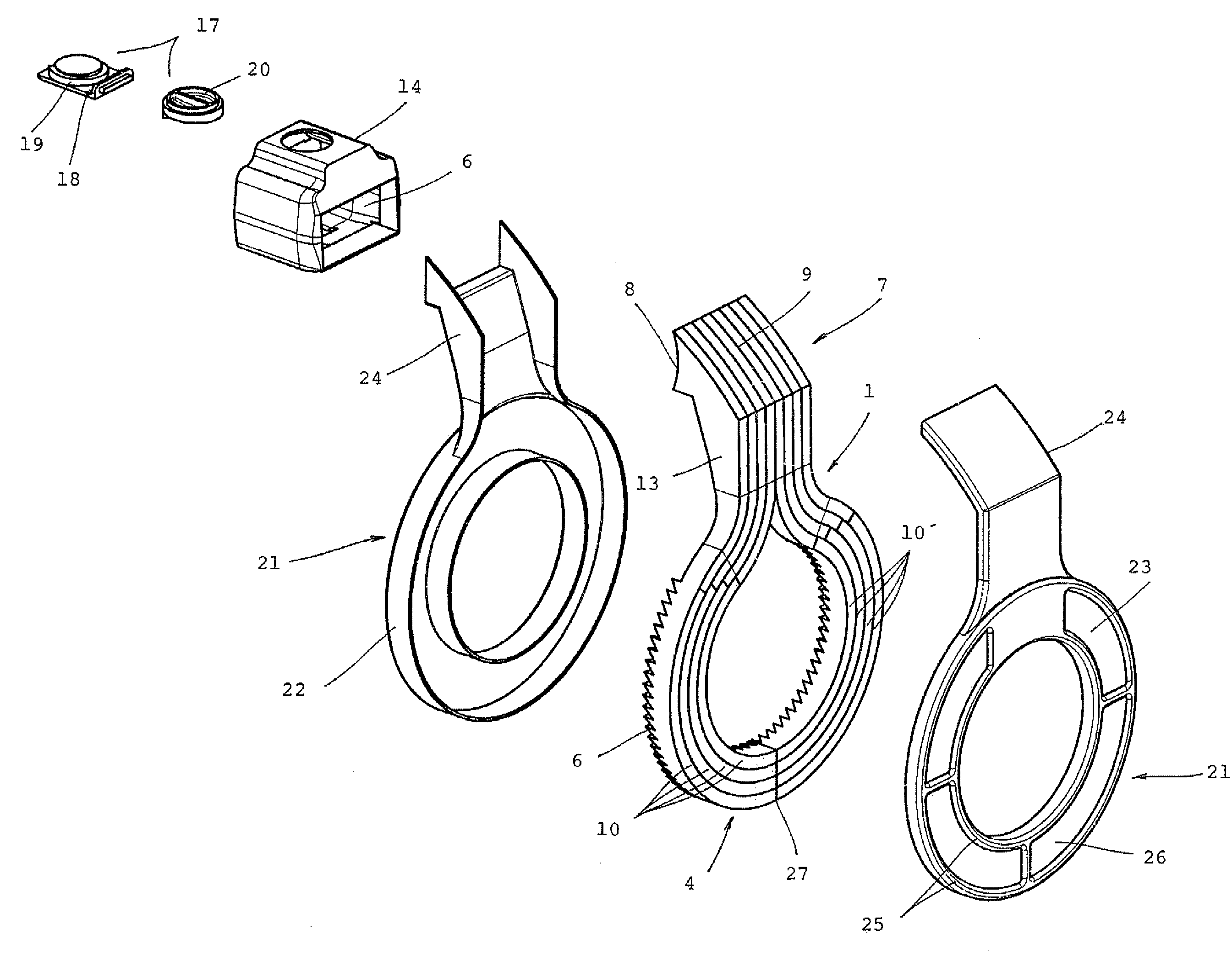
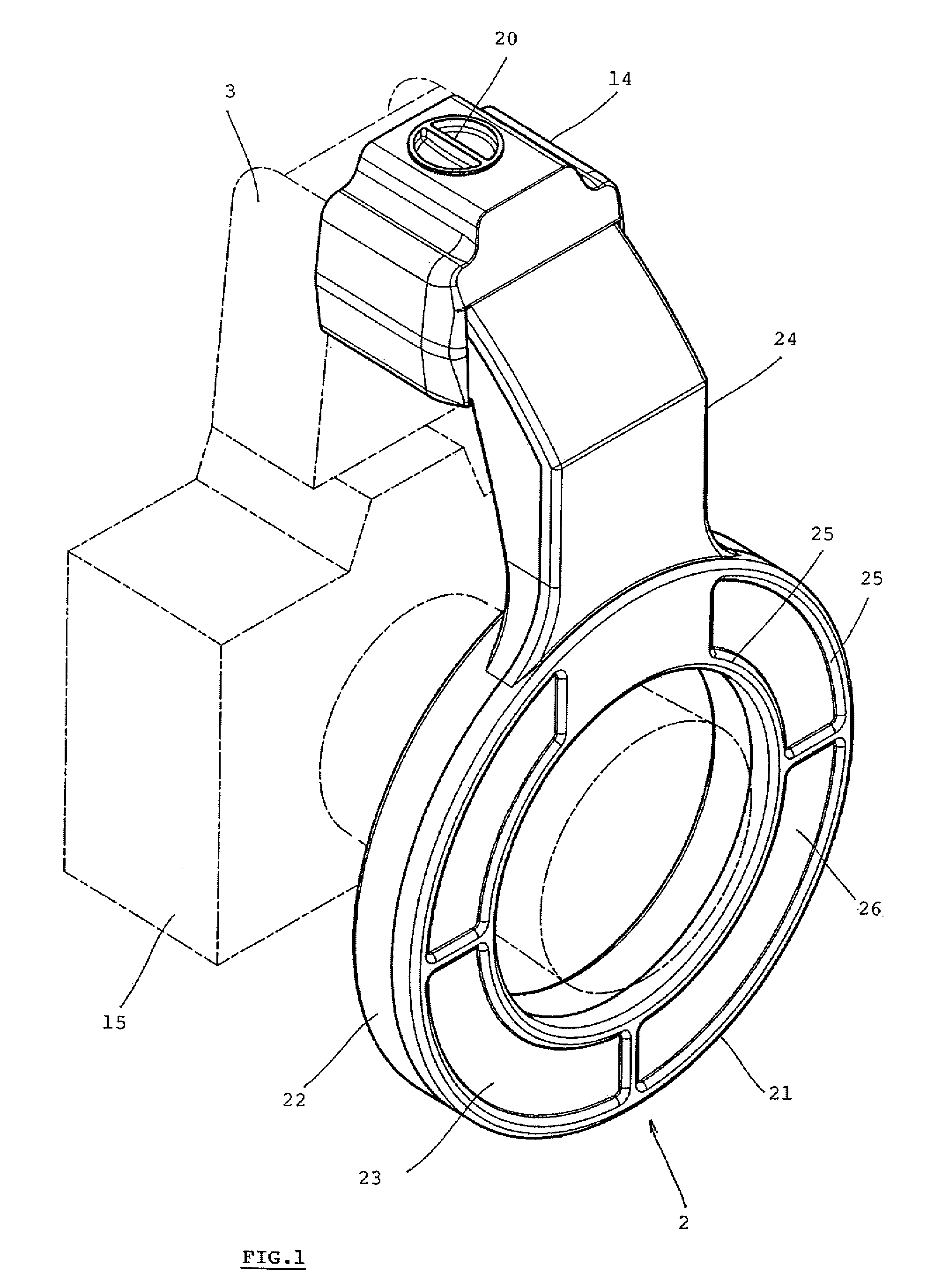
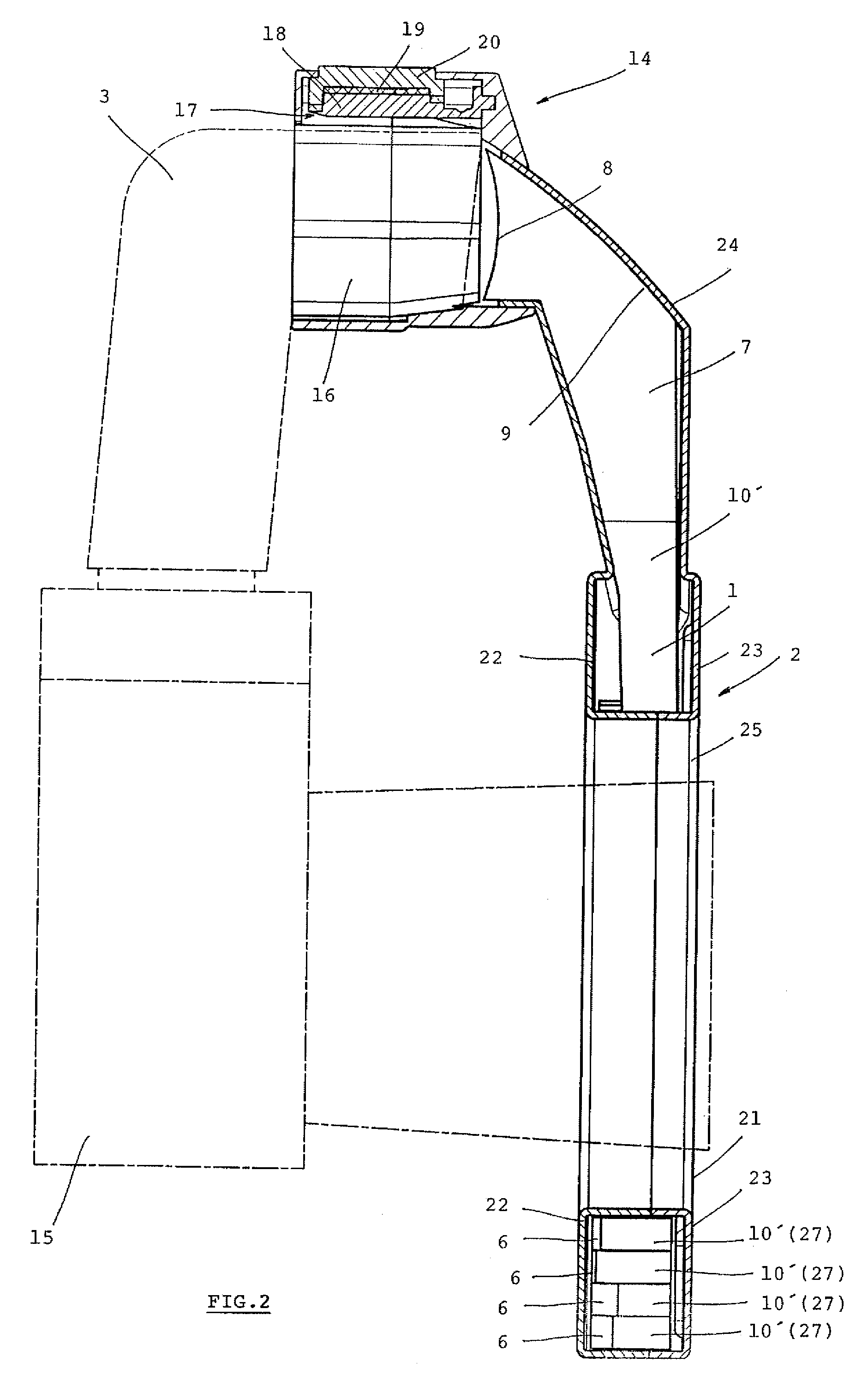
[0035]As shown in FIG. 1 and FIG. 2 the ring flash adapter 2 is attachable to an external flash 3 of the camera 15 using a clamping device 14 especially due to its low weight (less than 500 g) and small dimensions (the outside perimeter of the ring flash adapter 2 is 146 mm). The ring flash adapter does not charge the single-flash head of the flash 3 and it can be attached directly to it.

[0036]The ring flash adapter 2 consists of a circular body 21 with an extension 24 which ver...


PUM


Abstract

A ring flash adapter of the flash uses a clamping device attached to the external flash of the camera, and using the lightguide (1) the, light can be transmitted from the flash into circular body. The lightguide has a flat circle and a head with an incidence surface and a reflecting surface. The lightguide also has an even number of separate, parallel, inter-connected shaped belt segments inserted in the head. The foreside of the circle forms an emission surface; the rear side is provided with a system of “V” shaped teeth to reflect light on the emission surface.

Description

FIELD OF THE INVENTION[0001]The present invention relates to a ring flash adapter distributing light emitted from a point source light or bounded source light attached to the camera into a circular shape around the lens of the camera providing a soft diffusion of the flashlight in the space in front of the camera.PRIOR ART[0002]Ring flash adapters have been known that achieve the so-called soft light illumination, i.e. an illumination without marked shadows. These extensions are made as separate adapters for the classical external flashes, attachable to the camera; they are used to transmit the point source light to the circular, the annular emitting surface, respectively.[0003]According to the Czech author's certificate No. 221 782 “Reflecting ring to diffuse discharge from a classical flash into a circular area around the camera lens” ({hacek over (C)}UBAN, Petr) application date 22 Jul. 1981, PV 5566-81) a ring flash adapter has been known. It consists of an inner and outer cylin...

Claims


Application Information

Patent Timeline
Patent Type & Authority Patents(United States)
IPC IPC(8): G03B15/02F21V7/04G03B15/06
CPCG02B5/045G02B6/0036G03B17/56G03B15/03G03B2215/0539
Inventor ZYKA, DALIBOR
Owner ZYKA DALIBOR
Why Eureka
Try Eureka